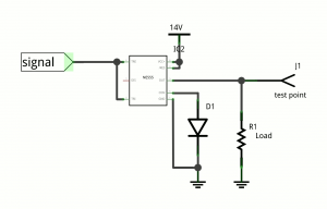
555 as a push-pull level shifter
A simple one-directional level shifter is easy to build out of an NPN transistor and two resistors in the common-emitter topology, if the application doesn’t need to sink as well as it sources—that is, if a significant output impedance is acceptable when the output is high. If low impedance is needed for high output, an additional PNP transistor and two resistors[1] can be added, again in common-emitter topology, to re-invert the signal, but then the output low has the impedance instead.
To both source and sink with comparably low impedances, the obvious solution, if you’re properly equipped, is probably CMOS: Two complementary MOSFETs configured to pull the output either up or down, with similarly low impedance either way—or, more likely, a CMOS logic IC that does the same thing, but in a more compact fashion.
Still, there are some possible issues:
- If you don’t keep a stock of (fairly well matched) N-channel and P-channel FETs around, you can’t really build a CMOS inverter out of them.
- If all you have are 74HC-series ICs, the output voltage must be from 2V to 6V. If your output voltage is, say, 13V, this is a no-go.[2].
- If the input high voltage is too much lower than the output voltage, a logic high may not register properly. A preliminary low-to-high shifter (such as the single-sided NPN thing from before, 3 parts) would be needed for each input.
- If the input high voltage is too much higher than the output voltage, a logic high may do some damage to the IC. A preliminary high-to-low shifter (such as a resistive divider, 2 parts) would be needed for each input.
Incidentally, constructing a CMOS-like complementary output using discrete bipolar transistors is not advisable; even short input transitions can cause high and low transistors to be on simultaneously for a non-trivial amount of time, a condition called shoot-through, which results in a massive current spike likely to damage both transistors and possibly other components. One way to avoid this condition is to add a resistance between the high and low sides, but then we’re back to the original problem. Shoot-through is evidently less of a concern with CMOS, partly because the FETs involved have better tuned and matched thresholds, and partly because a MOSFET is less subject to self-destruction via thermal runaway than a BJT.
Wanting to prototype something with an oddball push-pull 3.3V-to-13V switch led me to concoct an experiment using only stuff available at a reasonably well-stocked Radio Shack[3], with particular attention to ICs that provide push-pull outputs. So far I’ve tried configurations based on the original 555 timer[4] and the TL082 op amp.
My first experiments with the TL082 in Schmitt trigger configuration were not promising, but I’m suspicious something may have been connected wrong; the logic low never went below 1.15V, which happens to have been the reference voltage, half of 3.3V. Either way, the supply voltage had to read 17.3V for a high output of 13V.
In contrast, the 555-based Schmitt trigger appears to be a workable solution, as long as you can drive the chip 1.5V higher than the desired high output.

555 as a level shifter in just two parts (not including the load). Output is a roughly fixed amount below Vcc.
The output stage of the 555 is a push-pull output, but it is implemented with bipolar transistors in a traditional style, meaning both high and low sides are NPN transistors. This works, but at the cost of about 1.5V from Vcc. If you can pay that cost, it should work nicely.
In my experiments with the pictured circuit, using 1K for the load, the output was 12.5V for a 14.0V input. Similarly, it went up to 13.0V for 14.5V input, and 5.0V for 6.5V.
Apart from the 555, there is a diode to set the control voltage. The CV pin is essentially the top split of a 5K:5K:5K resistive divider from Vcc to ground. The splits of this divider set the high and low thresholds of the Schmitt trigger; they are CV (default 2Vcc/3) and CV/2, respectively. A silicon rectifier diode is added from the CV pin to ground, forming a crude shunt regulator with the internal resistors. This sets CV to about 0.6V and the low threshold to about 0.3V. This is suitable to make the input accept a clean signal directly from a 3.3V or 5V CMOS logic output. Adding a second diode in series with the first would double those levels, making input from a somewhat noisy source or from 5V TTL practical. CV could similarly be set using a Zener diode (in reverse) or by constructing a voltage buffer, but at that point you may just want to order a more suitable part.
So, there you have it—an imperfect but still practical low-impedance level shifter in just two parts.
- [1]or one resistor, with caveats I haven’t fully investigated↩
- [2]If you have the older CD4000-series ICs, however, up to about 18V is possible, as long as the inputs are brought within range.↩
- [3]For those of us who don’t have 24 hours to wait for progress.↩
- [4]Not the TLC555 they also carry, which may work better or worse.↩