First of all, I got the demo USB peripheral running. The thing has a button and a light; software on a Windows PC can switch the light and read the button. Also, in a surprisingly unrelated fashion, I had a lovely experience at Fry’s yesterday that somehow made me optimistic on behalf of the casual hobbyist. I shall describe both forthwith.
Tour
Control systems and you
Somewhat out of my current character, I lead with a lyric from They Might Be Giants:
Turn it up, turn it down
Turn it up when the cold brings you down
When the heat bothers you turn it down
Turn it up, turn it down— They Might Be Giants, “Thermostat”
This is a song about a thermostat, a brilliant device contrived in 1883 to either turn off or turn on a heating/cooling system in order to favor a certain temperature. The traditional version of the thermostat is among the simplest examples of a negative-feedback control system, a very important class of device.
An “on-off” control system basically repeats the following ad infinitum. The following example is for a thermostat controlling a heater (with a generalized version in parentheses).
- Is the current temperature the same as the temperature we want? (Is the current state the same as—or similar enough to—the desired state?)
- If so, good—stop here and check again after a certain period of time or as soon as there is an indication that this may no longer be the case.
- If not, continue.
- Which direction, higher or lower, is the desired temperature relative to the current temperature? (How is the current state different than the state we want? Which direction should we be going?)
- If the right direction is higher, am I already heating? If lower, am I already not heating? (Am I already moving in the right direction?)
- If so, then we’re already doing what we need to be doing. (Our effort is already in the right direction.)
- If not, switch off (if on) or on (if off). (Switch our effort to the right direction.)
- Start over.
Note that the typical thermostat is an on-off control, meaning that there are exactly two modes to its operation—0% and 100%. In the middle of winter, when it’s 68°F in your house and you decide to crank it to 78°F, well, first of all, you must like it hot and enjoy high energy bills; 68’s always fine in my house. Anyway, you as a human know that you’ve turned up the set point by 10 degrees, which is a lot to do at once. What you may or may not have realized is that your furnace isn’t making any special effort to work faster than if you’d only turned it up 2 degrees. It’s just going to stay on as long as it takes to do its job and then kick off.
This is because an on-off system asks “if I’m too far in either direction, which direction?” but not “and by how much?” This is the domain of a linear control system.
One might liken a linear control system with a human being with his foot on the accelerator pedal of a car. (For the time being, we’ll ignore that the brake is also pretty handy for slowing down a car.) The new process is as follows:
- Is my current speed the speed I want? (Same as 1 above.)
- If so, good—stop here and check again after a certain period of time or as soon as there is an indication that this may no longer be the case.
- If not, continue.
- Which direction, faster or slower, is the desired speed relative to the current speed? (Same as 2 above.)
- If faster, push the pedal harder (if possible).
- If slower, ease off the pedal (if possible).
- In inexact terms (this is important), how different than the desired speed is the current speed? (What is the error, the magnitude of the necessary change?)
- If the desired speed is a little faster, push the pedal a little harder.
- If the desired speed is a lot faster, push the pedal a lot harder.
- If the desired speed is a little slower, ease off the pedal a little.
- If the desired speed is a lot slowed, ease off the pedal a lot.
- Start over.
What’s remarkable about a system like this is that it’s inexact by design. For example, if I’m driving 60mph and need to 70mph, I’m going to push the pedal harder. But how much harder? Can I state it with an exact measurement of radians per mile per hour? No. (It could possibly be done, but I hope nobody is that bored.) So I just push the pedal (control) and see what happens (feedback). If I end up too slow, I push harder. If I undershoot, I let up on the pedal. This trial-and-error is called oscillation and a system generally benefits from it being kept to a minimum.
The system seems to work in situations where
- the directions of feedback and control have a consistent relationship; e.g. pushing harder always means increase in speed and, conversely, an increase in speed requires pushing harder
- the magnitude of change at the control is at least somehow proportional to the magnitude of the resulting change in the feedback; e.g. pushing a little or a lot harder means going a little or a lot faster, respectively, with the ratio of change at the control to the change at the feedback being adjusted on the fly as necessary; if we push the pedal a little and the car bolts, we adjust our definitions so that pushing the pedal a little means a much smaller push than before
One application of this that I consider fun is a phase-locked loop (PLL), which is able to arbitrarily multiply a clock signal from e.g. a crystal. I’ve never messed with one directly, but the ones in some of the Microchip PIC devices are able to bump the 20MHz CPU clock to a whopping 96MHz, which is then divided (a much simpler operation) to 48MHz in order to implement the onboard USB peripheral.
If the driver analogy above made any sense, then PLLs are a piece of cake: For every 20 million pulses that are generated by the crystal, it has to generate 96 million pulses. Or, if you’re clever, for every 5 pulses from the crystal, generate 24—probably easier to count that way. It’s by no means trivial, but it’s straightforward.
Control: The PLL train is produced by a voltage-controlled oscillator (VCO), which is able to generate really, really fast pulse trains but must be tuned on the fly. (This can be replaced with some other form of controlled variable-frequency oscillator.) When it’s first kicked, it delivers a pulse train that is most likely not the right frequency.
Pre-processing: To correct it, the first thing we do is have available a frequency divider for each of the crystal (divide by 5) and the VCO output (divide by 24). A frequency divider is dead simple; for example, to divide a pulse train by 5, just do a transition on output for every 5 you count on input. Simple! Our goal is to make the pulse train of the crystal/5 match the VCO/24 as precisely as possible. When they match, the VCO output is exactly 24/5 of the crystal’s input. Then, we just pass the VCO output directly to wherever it’s needed.
Error: A phase detector sets about finding the difference between the VCO/24 and the crystal/5 trains, noting where the trains are not the same width as well as where they don’t line up even if they are the same frequency. A low-pass filter cleans up places where the difference is so slight that it should be ignored (i.e., where the differences are so insignificant that acknowledging them would hurt rather than help).
Feedback: The error value from the phase detector is fed back into the VCO.
And, as they say, viola…96MHz from 20MHz. Nifty, right?
If I get my way this weekend, I’ll have turned a PIC18F4550 into a bona fide peripheral. Just figured that a note or two about how this is possible might be in order…
Kits at the Radio’s Hack
On my way to get a haircut that ended up being what one could rightly call “silly” or “mediocre”, I stepped into Radio Shack for a moment. They’ve gotten some press recently for their renewed appeal to the electronics hobbyist crowd that it lost some time ago by downplaying its component offerings and taking a nearly exclusive focus on consumer items that are not that great, too expensive, or both. (And, more recently, on mobile phones.) They must have been on the down tick even before my first encounters with electronics back in elementary school—I recall my dad telling me that it’s usually a bad idea to get something there if it could be found anywhere else. Some of the folks on Usenet like to call it “Rat Shack”.
And it was the truth, because if there was anything slightly weird I needed that they didn’t stock, I was out of luck until I got together enough allowance to place an above-minimum order at Electronic Goldmine or Mouser. (Note that my component catalog of choice is currently Newark, followed by Allied. Electronic Goldmine is still fun if you have patience and a sense of humor.)
Anyway, they’re trying to appeal to the hobbyist again. Even if they don’t end up doing so well with it, their heart’s in the right place. With that in mind, I stepped into the store, politely blew off the salesperson (you know you’ve done it), and checked out what they had.
A lot of it was the same stuff they’ve always had, stuff that might be handy to buy in a pinch but that it’s a better idea to wait out a mail order for.
The first new thing that caught my eye was a series of kits by Velleman, a European company that appears to do kits and oscilloscopes among other things. The offerings were mostly simple light and/or sound circuits based on discrete components, but look like they’d be entertaining to put together, and the very simplest ones come in under $10, which is certainly a fair sell for someone not up to circuit design yet.
They also had a couple of cool-looking kits based on microcontrollers. I don’t recommend that you buy either one, but I’ll describe them before I tell you why.
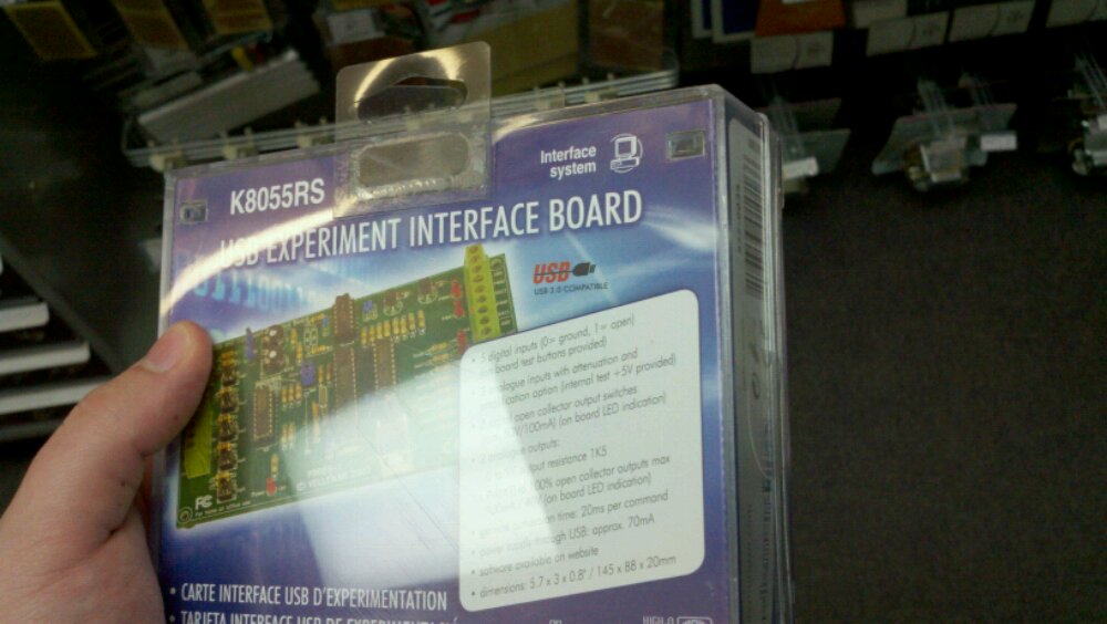
The USB Experiment Interface Board has a set of screw terminals (they accept either solid or threaded wire without a lot of fuss) to I/O pins on the micro (advertised are 5 digital in, 8 digital out, 2 analog in, 2 analog out). If they did the host software correctly, this could be a very fun toy. I know that back when I was 10, the ability to make my circuit talk to QBasic was an extremely cool thing to do. I believe I had managed to get together one circuit that I’d read about in Electronics Now and make it signal to the parallel (or was it serial?) port whether there was something between an IR LED and a phototransistor, but I certainly didn’t know how the code or the electrical interface actually worked.
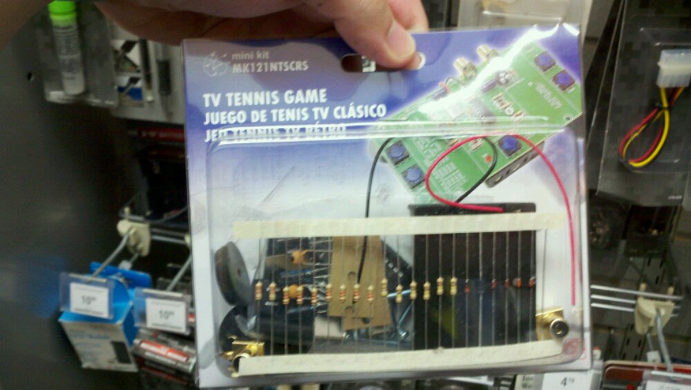
Here’s one with even more mystique: The circuit, by way of its microcontroller, implements a PONG-like game by reading input from on-board microswitches and then modulating its current state into an analog NTSC signal for your (hopefully old enough) TV. In principle, it’s extremely similar to the original PONG itself (the major differences being that in PONG the controllers were analog and the CPU was not a microcontroller but an entire fleet of discrete logic chips).
So, why do I think you should not buy these? Let’s revisit the above with a couple of very important stats:
First: Microcontroller. According to the spec sheets, the USB interface uses a PIC16C745, and the game uses a PIC16C505. That “C” that comes after the “16” means that these chips are single-write only—the program in the micro comes pre-written and can’t be edited. That’s a massive fail on the kit makers’ part in my opinion; the community is all about being able to fiddle with stuff, and you can’t mess with the micros in these kits. Theoretically, you could replace the chip with its related flash-programmed “F” variant, but haven’t you already bought the kit? This brings us to…
Second: Price. The game kit costs $40. The USB interface is $60. Wow. Really?
Okay, so for those of you who aren’t close enough to the community to see the obvious conclusion, please allow me to introduce you to what you should buy instead of either of the above: the mighty Arduino.
I understand that people really like to gush about this thing, but the idea is actually pretty great: You have a hardware platform based on a cheap Atmel micro, then you have a software platform based on a very C-like language via a very easy-to-use IDE. You connect the two together using the onboard USB-serial adapter, and disco—it’s at least equivalent to the aforementioned USB interface (except for the screw terminals, which aren’t hard to add). The price? Without looking too hard, I found one option for $26, and I’m sure it can be found cheaper. Since the hardware designs are free (as in liberty) there are multiple manufacturers of the board itself and clones thereof.
And the community for the thing is live and virulent. If you want help, there’s sure to be someone to give it to you.
(Oh, also: You want PONG? You’ve got PONG.)
Before I take off, here’s something that isn’t a kit:
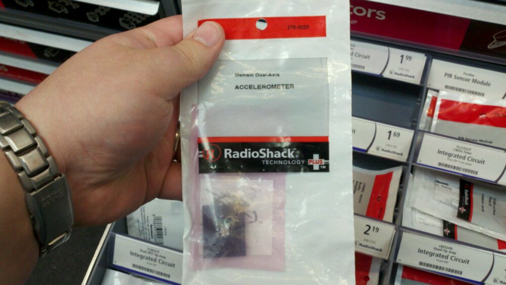
If you’re into accelerometers (a kind of physical motion sensor), RS is selling one from Parallax which is just a Memsic 2125 mounted on a tiny board with pins so mortals can actually use it—the 2125 is an LGA device, thus requiring some equipment to solder than the typical hobbyist couldn’t be expected to have on hand. They sell it for $37. Parallax seems to sell it directly for $30. If you want something similar without the overhead, similar stuff is available at Newark, but most of it is not hand-solderable. The majority are LGA devices, but a select few dual-axis devices are available in SOIC, a surface-mount form which I’ve had success soldering by hand (by slathering on the solder and then wicking the excess back off), starting around $13 in singles. And of course even if you can solder them by hand, you’ll still have to have a board made up to solder the thing onto. If you don’t have the stuff for making PCBs, it’s entirely possible that in this case the Parallax device is worth the extra money.
That’s it. Until later…