PIC programmers: The electrical part
ICSP in general
From the perspective of actual information to be transferred, an ICSP (in-circuit serial programming) programmer for a PIC microcontroller is not terribly complicated. As with a CPU, there are operands and instructions that must be issued in a particular order.
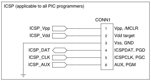
General pinout of PIC ICSP connector
As with a serial shift register or SPI device, there are two lines—one data line (pin 4, ICSPDAT) to carry the information plus one clock line (pin 5, ICSPCLK) to indicate when that information is valid. In ICSP, the data line is bidirectional so that the programmer can read memory from the target PIC; the programmer should be prepared for that.
There are also the Vpp (pin 1) and Vdd target (pin 2) lines. Vpp must be able to assert either 0V or the programming voltage (13V for most targets). Similarly, Vdd must be able to assert either 0V or the target Vdd (often 5V, but may vary). The switching times must be kept to a minimum; for example, a 16F88 target specifies a Vpp rise time of 1µs.
Vss (pin 3) exists but is not usually switched.
Finally, there is AUX (pin 6), a plain output pin from the programmer to indicate LVP (low-voltage programming) instead of supplying the high voltage on Vpp. Programmers not supporting LVP tie this to ground via a resistor.
The application circuit itself, when presenting an ICSP header, must isolate the pins of the header from excessive capacitance or other interference so that the voltages and rise/fall times are as specified. If possible, the pins used for ICSP should be dedicated. If one or more of these pins is needed for I/O in the application, the circuit should be designed to give the ICSP higher priority (such as by connecting the ICSP header directly but connecting the application circuit via a resistor). If Vpp is connected to an RC slow start circuit (as /MCLR), it can also be isolated using a resistor or a Schottky diode.
Production programmers
The documentations for ICSP differentiates a prototyping programmer from a production programmer as follows:
A production programmer is capable of performing the verification step (i.e., reading back the contents of the target device’s memory as written) with target Vdd set to the minimum and maximum specified voltages of the application circuit.
A prototyping programmer…doesn’t.
This verification is intended to ensure that each memory location in question was either written or erased with a sufficient combination of voltage, current, and time to be reliably recovered.
As implemented by Ardpicprog
Ardpicprog is a project that specifies an ICSP-compatible prototyping programmer using an Arduino for the host computer connection and most of the programming logic.
On the one hand, if the application circuit is simple enough, or if you use the ZIF socket configuration instead of ICSP itself, the programmer circuitry could not get much less complicated, constructed only of three resistors and a single transistor, plus whatever 13V supply you have handy for Vpp[1]. If you’re in a hurry, this could be your pick.
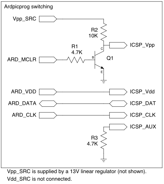
Switching circuitry for Ardpicprog (not shown: 13V linear regulator for Vpp_SRC, indicator LEDs, ZIF socket for non-ICSP use)
However, there are some issues that may prevent it from being generally applicable, at least for ICSP:
- ICSP_Vdd is driven directly from an Arduino I/O line. For non-in-circuit programming and for the very slightest of application circuits this is fine. But the absolute maximum DC current rating for that pin (ATmega168) is 40mA, so the Vdd pin on the application circuit might need to be extremely well isolated in order not to harm anything.
- ICSP_Vpp has a somewhat high impedance (R2) when outputting high. This might not be a problem in most situations, since the target’s Vpp pin is fairly high-impedance itself, but when programming I noticed that this line was closer to 12V when turned on.
- The programmer’s logic high voltage is the only target Vdd supported.
- If the programmer is 5V but the application circuit is designed for 3.3V (some PICs can do this), incomplete isolation on the application side could result in damage.
- If the programmer is 3.3V (some Arduinos and copycats can do this) but the application circuit is designed for 5V, programming would probably fail unless Vdd to the PIC device is well isolated and the PIC is of a model that supports 3.3V (such as 16LF88—note the L).
- The programmer is not properly buffered for a self-powered target. For one example, a 3.3V programmer with a self-powered 5V target would probably sustain damage from the current sunk by the ICSP_Vdd pin.
- Naturally, the programmer is not for production.
- LVP is permanently disabled. (This isn’t necessarily a bad thing; I’ve read that actually getting LVP to work is difficult.)
As implemented by PICkit 2
Microchip’s own PICkit 2 is a mostly production-capable PIC ICSP programmer. The designs for this 18F2550-based programmer aren’t free (in the sense of liberty), but the firmware and schematics have both been published and clones of the device are plentiful.
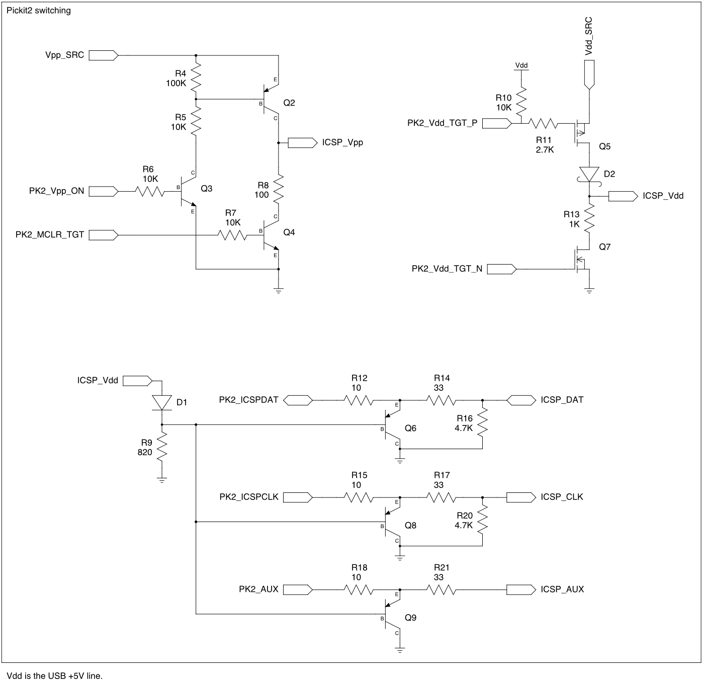
Switching circuitry for PICkit 2
While not nearly as simple as Ardpicprog, the switching for the PICkit 2 is not utterly complex, either.
- The Vpp switch uses a sort of push-pull, allowing both high and low voltages to come through with fairly low impedance. This is controlled by two lines, and the firmware must prevent both from being on at the same time to avoid shoot-through.
- The Vdd switch is similar, but uses MOSFETs, presumably to reduce voltage drop, and a Schottky diode to prevent reverse current from a self-powered target.
- A self-powered target is supported by turning off both push and pull in firmware.
- Whether self-powered or not, the actual target Vdd appears on ICSP_Vdd.
- The data, clock, and AUX lines are clamped, using PNP transistors, to be no higher than ICSP_Vdd. (The 18F2550 correctly reads 3.3V-level highs and lows even at 5V).
Perhaps the most interesting characteristic of the PICkit 2 is the onboard boost regulator.
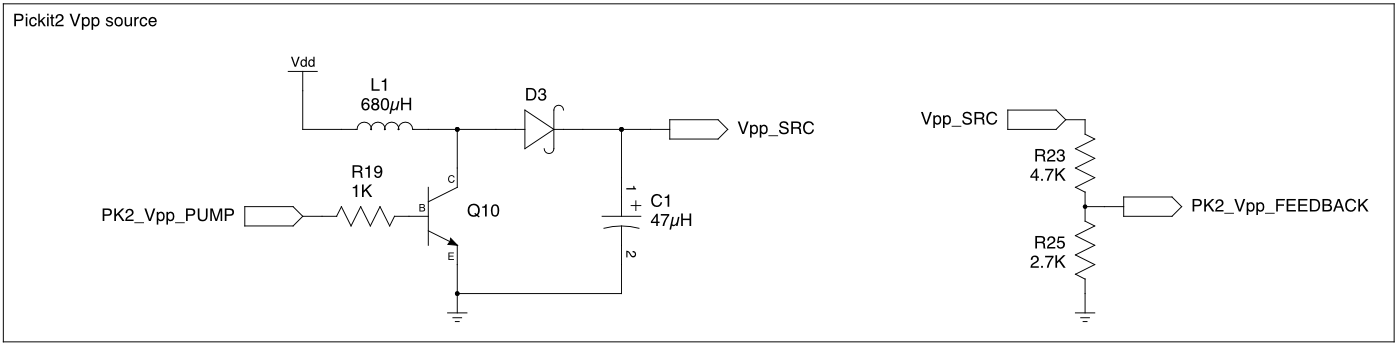
PICkit 2 Vpp boost regulator
Using a PWM output[2] (PK2_Vpp_PUMP) with an inductor, the programmer is able to produce and regulate the high Vpp voltage (Vpp_SRC) without a second supply. A resistive divider feeds back to an ADC input (PK2_Vpp_FEEDBACK), allowing the firmware to make adjustments to the PWM duty cycle.
This is by no means an original circuit, nor is it specific to PIC (I’ve gotten one working on an Arduino), but it is a useful inclusion.
What makes this a more-or-less production-capable programmer is its built-in adjustment for Vdd.
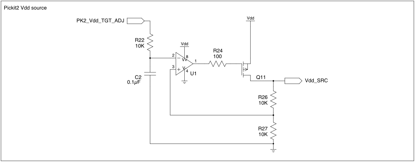
PICkit 2 Vdd buffer
A PWM output[3] (PK2_Vdd_TGT_ADJ) is used as a rough DAC by passing it through an RC lowpass (R22 and C2), resulting in a steady analog level. The op amp is configured to double the input, so the DAC must output half of the intended voltage. The PFET in the feedback loop increases the current capacity of the amp output.
The maximum target Vdd is less than the programmer’s Vdd due to drops that exist within the programmer. One workaround is to make the target self-powered; all of the lines are set up such that even a 6V target shouldn’t harm a programmer running at 3.3V[4]. By self-powering like this (with any programmer), it becomes more difficult to enter program mode with some targets: The timing requirements vary from device to device, but several of them require Vpp to rise a very short time[5] after Vdd initially rises. When the target is self-powered, ICSP_Vdd cannot be driven low by the programmer. There might be some secret to making this work that I just haven’t read yet.
It would also work to patch in a higher voltage (maybe 6-7V) to the source of the PFET instead of Vdd. For an actual PICkit 2, this would involve some messy hacking that would more likely ruin the device than improve it.
My own ideas
I’ve been toying with an idea to make a production-capable (or nearly-production-capable) programmer based on the principles of these designs plus some of my own ideas.
- Arduino implementation.
- This is partly because I think it’s funny, but mostly because it caters to impatience: If you suddenly need a PIC programmer, nobody sells a PICkit retail but at least RadioShack and Fry’s have some variation of Arduino for sale.
- Full support for any combination of 3.3V or 5V programmer and target.
- Some Arduinos and other development boards are pushing for 3.3V logic. I say, sure, why not?
- Push-pull switching for Vpp and Vdd.
- I think the Vpp switch on PICkit 2 would be a good model for both Vpp and Vdd. I don’t dislike MOSFETs, but I have a zillion PNP and NPN devices and only a very small number of FETs.
- Using the PK2 Vpp switch for Vdd would allow use of e.g. 5V target with 3.3V programmer. Q2 and Q3 serve as a sort of level shifter.
- Full level shifting for I/O lines.
- A level shifter I’ve been playing with in a simulator[6] starts with a buffered 1V supply (2 silicon diodes, 1 Schottky diode, 1 NPN, and input voltage of 2V or higher) through 470 ohms to the base of an NPN. The input is the emitter of that transistor, and the output is the collector, which is pulled up to the desired output voltage.
- A bidirectional variation of this[7] is to use 2 NPNs with the bases tied together (to the same 1V through 470 ohms) and cross couple each collector to the other emitter, finally pulling up each side to the desired voltage.
- Unlike the common 1-NFET bidirectional shifter, this design does not require the advance knowledge of which side will be higher, so the target is allowed to be either higher or lower than the programmer.
- Since these shifters pull up rather than down, firmware or other circuitry expecting pull-down behavior would need to be adapted.