Archive

Non sequitur

In Perl, we have some funny (and often contraindicated) features that are just useful enough not to excise them from the language. One of them is that the sort and grep operators (which reorder and filter lists, respectively) return aliases, rather than copies, of the original array elements whenever possible. Because of this, the original array can be modified through the sorted/filtered result.

my @a = qw/w o r d/;
say sort @a; # 'dorw'
 
# Note that perl sort is not in-place.
say @a; # 'word'
 
# Change index 3 of the sort result, which is 'w', to a 'z'
(sub { $_[3] = 'z' })->(sort @a);
 
# The change is reflected in the original
say @a; # 'zord'

Getting this functionality into a non-builtin sub is not straightforward—I haven’t determined any way to return an array directly that retains its linkage to the original. However, it’s pretty easy to do something almost as good (or possibly better): Return an array reference that can do the same thing. The trick to this is that @_, the parameters array for a function, consists of aliases to its parameters, but a reference to it can be taken and returned.

sub parameter_alias_array_ref { \@_ }
 
sub dumb_alternative_sort {
	parameter_alias_array_ref(sort @_);
}
 
my @a = qw/w o r d/;
my $s = dumb_alternative_sort(@a);
say @a; # 'word'
say @$s; # 'dorw'
$s->[3] = 'z';
say @a; # 'zord'
say @$s; # 'dorz'

One place this might be useful is in tandem with the so-called “Schwartzian transform”, a Perl idiom for sorting a list based on some projection of the elements rather than the elements themselves. The premise is that, for some function foo(), we would like the result of

sort { foo($a) cmp foo($b) } @array

but, foo() being somewhat expensive, we would rather compute its value for each element only once rather than the multiple times that would be done this way. So, each row is mapped into a 2-tuple containing the value itself and its projection. The sort is performed ordering by the latter value, then the projection is stripped, leaving only the original value. That looks like the following:

# Note that the order is the reverse of what is described above
map { $_->[0] } sort { $a->[1] cmp $b->[1] } map { [$_, foo($_)] } @array
# Intuitive order using temp variables
# Append projection
my @tmp_appended = map { [$_, foo($_)] } @array;
# Sort by projection
my @tmp_sorted = sort { $a->[1] cmp $b->[1] } @tmp_appended;
# Strip projection
my @result = map { $_->[0] } @tmp_sorted;

Note, however, that this result is a copy, not an alias to original elements.

One workaround would be to have the transform return an array of scalar refs to the original array elements. That would look like this:

my @refs =
	map { $_->[0] }
	sort { $a->[1] cmp $b->[1] }
	map { [\$_, foo($_)] }
	@array;
 
# Assign to whatever the 4th element of the result was
${$refs[3]} = 'idk';
 
# Get the results as a plain array copy
my @result = map { ${$_} } @refs;

Ugly and unnatural. But what if we had some way to transform an array of scalar refs into an array aliased to those scalars?

my $ref_result = scalar_refs_to_array_ref(
	map { $_->[0] }
	sort { $a->[1] cmp $b->[1] }
	map { [\$_, foo($_)] }
	@array);
 
# Assign to whatever the 4th element of the result was
$ref_result->[3] = 'idk';
 
# Get the results as a plain array copy
my @result = @$ref_result;
 
# OR, just use @$ref_result directly!

The implementation follows. The fact that @_ aliases the parameters is heavily abused here. The parameters are aliased a few at a time because the dereferenced scalars must be passed directly and explicitly; the obvious shortcut (using map) removes the magic we’re trying to exploit. An alternative would be to construct an explicit list in the form of a string and use eval to alias all of the elements at once. This isn’t an altogether bad idea, but it’s avoided here.

sub parameter_alias_array_ref { \@_ }
 
sub scalar_refs_to_array_ref {
	my $result = parameter_alias_array_ref();
 
	my $count = 0;
 
	# The seemingly straightforward way to do this would be map { $$_ } @_, but
	# that doesn't preserve the aliasing magic that we need.
 
	while(@_) {
		my @part = splice(@_, 0, 16);
		$count += @part;
		my $pa = parameter_alias_array_ref(
			${$part[0]}, ${$part[1]}, ${$part[2]}, ${$part[3]},
			${$part[4]}, ${$part[5]}, ${$part[6]}, ${$part[7]},
			${$part[8]}, ${$part[9]}, ${$part[10]}, ${$part[11]},
			${$part[12]}, ${$part[13]}, ${$part[14]}, ${$part[15]},
			);
		$result = parameter_alias_array_ref(@$result, @$pa);
	}
 
	# Trim excess introduced when the length is not a multiple of the part
	# length above.
	splice(@$result, $count);
 
	$result;
}

EDIT: You might have noticed that up to 15 undefined array elements (specifically, the remaining undefined elements when there are fewer than 16 in the last part) are dereferenced as scalars when the last part of the input is processed. Yet the code still works perfectly. Why?

It’s a semi-obscure bit involving what’s known in Perl as autovivification: If an undefined scalar variable (say, $somevar) is dereferenced as if it were a scalar ref ($$somevar), an anonymous scalar is automatically created and a reference to it is assigned to the variable (something like { my $tmp = undef; $somevar = \$tmp }), and only then is it dereferenced.

Note that this only works if what is dereferenced is a variable; something like ${(undef)} always breaks. In our case, the variable would be $part[n] for any n greater than or equal to the size of the last part; an array element counts as a scalar variable.

Unless you find that the autovivification of up to 15 scalars is consequential performance-wise (it probably isn’t), the code can be left as is. Otherwise, a workaround would be straightforward.

Reflow soldering typically makes use of solder paste, which is fairly easy to work with but has a short shelf life and can only be reasonably purchased in quantity (read: I can’t justify buying any). I performed a very loose experiment this weekend in using the more traditional coiled solder for reflow.

I’d seen two important articles whose advice I sought to combine. One was for the concept of performing the reflow itself using plain solder and a hot air station. I have no hot air station; what I do have is a reflow skillet,  but that article deals in solder paste.

With these concepts in mind, and with a fresh supply of SMT components purchased in anticipation of building my Bus Pirate, I decided on an extremely simple circuit, an LED and resistor in series, and got to work.

Please note that mistakes were made; don’t try any of this until you’ve read the whole thing and know what not to repeat.

I started by scratching out a PCB. I used a box knife instead of etching because I didn’t want to delay the experiment with an uncertainty and, given my more recent failures, it seemed like etching was more likely to be a waste of time than I could allow. In this case, I scratched the outline of a trace roughly 3mm wide across the length of the board, and sliced across it in two places, one for each component.

I colored all of that side of the board except the six points that needed to remain exposed with a Sharpie, thinking it might work as a solder mask. (It didn’t. Read on.)

I used my soldering iron to apply solder to each of the six points I left uncovered; this would be the solder to be reflowed.

0309141748

Sharpied and soldered. Only one of these was a good idea.

After it cooled enough to handle, I placed the components atop the now-solid solder on their pads. Both components were 0603[1], roughly the size of a sesame seed, and nudging them around without flipping them over is difficult, especially with my unsteady hands. One also must take care that the part stays in place instead of sticking to the tweezers. This was a trial of patience.

At this point it was necessary to apply flux; the original flux in the core of the solder itself would have already dissipated when soldered the first time. The flux itself exposed the main two errors that I made in this process:

  • Components should probably be placed after the flux. I had expected the flux to be liquid like in the videos, but at somewhat below room temperature (the temperature of the workspace), it is most sincerely a paste, and it is easily stiff enough to knock the already tenuously-placed components out of place. Bigger components are probably less of a problem since they are already easier to place.
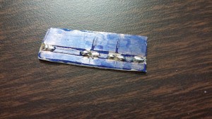
  • Sharpie does not work as a solder mask, at least for reflow; flux readily dissolves the ink. Actually, the ink did seem fairly effective when I was applying the solder with the iron, but it started to lift with the paste, and once the flux was warm enough to flow the whole board was a tacky, blue mess. It naturally follows that the solder wicked all the way up the traces, as evident from the picture, but in this case that wasn’t a problem.

Once everything was relatively ready, I put the board in the pan[2] and turned it up to 375°F, which is reportedly slightly above the melting point for my solder. The board was placed off-center in the ring-shaped area directly over the heating element. The flux quickly turned liquid. After only a couple of minutes, the solder liquefied as well, and once it all seemed thoroughly reflowed, I turned off the heat, leaving the board in the pan as it cooled[3].

0309141821b

Nice board, if you like your flux tinted.

I brushed off the excess flux and scratched through the remaining film to the contact spots I made for power to the board. I connected up the gator clips and powered up. Nothing in either direction. Then I realized that I’d left the plane on the far side of the board untouched, causing the clips to be shorted. Whoops.  Touching the clips to the points on the top side of the board allowed it to function properly.

It can be done!

Stuff I’ll keep in mind for next time:

  • If more than a little solder ends up on a pad, it should probably be wicked off. A little is necessary; a lot can be problematic for placement.
    • I’ve also read that, for small enough parts, unevenness between the pads can cause the component to stand on end instead of soldering properly, called “tombstoning”. Let’s try to avoid the parts that are especially prone (the hard-to-imagine-ly small 0402 and 0201 parts).
  • Flux before placing. It may help keep the components in place.
  • Experiment with mask materials before attempting to use one again.

Thanks to Club Cyberia for being a place other than my garage where I can make this stuff happen.

  1. [1]0.06 by 0.03 inches
  2. [2]To be perfectly honest, the board was in and out of the pan at least twice as I noticed things I’d forgotten to do, but was only allowed to fully heat when ready.
  3. [3]Cooling or quenching it suddenly is likely to damage the components or reduce the structural integrity of the connections.

Will try to leave the extraneous details out so that this actually gets posted.

The Steel Sandwich hasn’t been touched since December, but a test at 450°F, wrench-tightened, for 30 minutes gave the best transfer yet—except that the copper was so oxidized as to be purple. But I didn’t try to etch it. It might have still worked. Will pick that one up at some point.

I got a credit for the Dangerous Prototypes free PCB drawer and snagged a bare Bus Pirate 3.8 board. If you haven’t heard of the Bus Pirate, look it up—it’s a fine digital exploration, analysis, and prototyping tool.

I have an order in for all of the parts, plus a couple of hand tools I needed and some parts that I think will be useful for the universal PIC ICSP adapter thing I keep touching on here. I hope I can keep my hand steady enough to solder all of those surface-mount parts.

I’ve also ordered a few of the PIC16F527, a relatively recent addition to the PIC 12-bit line, which is only a small amount more expensive than the PIC16F57 (the current cheapest 16F) and has more I/O pins and an onboard precision 8MHz oscillator. That last bit means saving a couple of cents from omitting the external RC, improving the viability in timing-sensitive applications, and simplifying PCB layout. The additional I/O also means that, in some cases, a shift register (like 74HC595) or port expander can be eliminated. Overall, probably worth the extra 19 cents.

Finally, for Valentine’s Day, my wife initiated my membership to Club Cyberia, the only hackerspace I’ve ever heard of in this vicinity. I’m interested to see what difficulties this might help alleviate.

ICSP in general

From the perspective of actual information to be transferred, an ICSP (in-circuit serial programming) programmer for a PIC microcontroller is not terribly complicated. As with a CPU, there are operands and instructions that must be issued in a particular order.

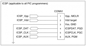
ICSP

General pinout of PIC ICSP connector

As with a serial shift register or SPI device, there are two lines—one data line (pin 4, ICSPDAT) to carry the information plus one clock line (pin 5, ICSPCLK) to indicate when that information is valid. In ICSP, the data line is bidirectional so that the programmer can read memory from the target PIC; the programmer should be prepared for that.

There are also the Vpp (pin 1) and Vdd target (pin 2) lines. Vpp must be able to assert either 0V or the programming voltage (13V for most targets). Similarly, Vdd must be able to assert either 0V or the target Vdd (often 5V, but may vary). The switching times must be kept to a minimum; for example, a 16F88 target specifies a Vpp rise time of 1µs.

Vss (pin 3) exists but is not usually switched.

Finally, there is AUX (pin 6), a plain output pin from the programmer to indicate LVP (low-voltage programming) instead of supplying the high voltage on Vpp. Programmers not supporting LVP tie this to ground via a resistor.

The application circuit itself, when presenting an ICSP header, must isolate the pins of the header from excessive capacitance or other interference so that the voltages and rise/fall times are as specified. If possible, the pins used for ICSP should be dedicated. If one or more of these pins is needed for I/O in the application, the circuit should be designed to give the ICSP higher priority (such as by connecting the ICSP header directly but connecting the application circuit via a resistor). If Vpp is connected to an RC slow start circuit (as /MCLR), it can also be isolated using a resistor or a Schottky diode.

Production programmers

The documentations for ICSP differentiates a prototyping programmer from a production programmer as follows:

A production programmer is capable of performing the verification step (i.e., reading back the contents of the target device’s memory as written) with target Vdd set to the minimum and maximum specified voltages of the application circuit.

A prototyping programmer…doesn’t.

This verification is intended to ensure that each memory location in question was either written or erased with a sufficient combination of voltage, current, and time to be reliably recovered.

As implemented by Ardpicprog

Ardpicprog is a project that specifies an ICSP-compatible prototyping programmer using an Arduino for the host computer connection and most of the programming logic.

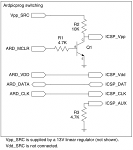
On the one hand, if the application circuit is simple enough, or if you use the ZIF socket configuration instead of ICSP itself, the programmer circuitry could not get much less complicated, constructed only of three resistors and a single transistor, plus whatever 13V supply you have handy for Vpp[1]. If you’re in a hurry, this could be your pick.

Ardpicprog switching

Switching circuitry for Ardpicprog (not shown: 13V linear regulator for Vpp_SRC, indicator LEDs, ZIF socket for non-ICSP use)

However, there are some issues that may prevent it from being generally applicable, at least for ICSP:

  • ICSP_Vdd is driven directly from an Arduino I/O line. For non-in-circuit programming and for the very slightest of application circuits this is fine. But the absolute maximum DC current rating for that pin (ATmega168) is 40mA, so the  Vdd pin on the application circuit might need to be extremely well isolated in order not to harm anything.
  • ICSP_Vpp has a somewhat high impedance (R2) when outputting high. This might not be a problem in most situations, since the target’s Vpp pin is fairly high-impedance itself, but when programming I noticed that this line was closer to 12V when turned on.
  • The programmer’s logic high voltage is the only target Vdd supported.
    • If the programmer is 5V but the application circuit is designed for 3.3V (some PICs can do this), incomplete isolation on the application side could result in damage.
    • If the programmer is 3.3V (some Arduinos and copycats can do this) but the application circuit is designed for 5V, programming would probably fail unless Vdd to the PIC device is well isolated and the PIC is of a model that supports 3.3V (such as 16LF88—note the L).
    • The programmer is not properly buffered for a self-powered target. For one example, a 3.3V programmer with a self-powered 5V target would probably sustain damage from the current sunk by the ICSP_Vdd pin.
    • Naturally, the programmer is not for production.
  • LVP is permanently disabled. (This isn’t necessarily a bad thing; I’ve read that actually getting LVP to work is difficult.)

As implemented by PICkit 2

Microchip’s own PICkit 2 is a mostly production-capable PIC ICSP programmer. The designs for this 18F2550-based programmer aren’t free (in the sense of liberty), but the firmware and schematics have both been published and clones of the device are plentiful.

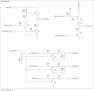
Pickit2 switching

Switching circuitry for PICkit 2

While not nearly as simple as Ardpicprog, the switching for the PICkit 2 is not utterly complex, either.

  • The Vpp switch uses a sort of push-pull, allowing both high and low voltages to come through with fairly low impedance. This is controlled by two lines, and the firmware must prevent both from being on at the same time to avoid shoot-through.
  • The Vdd switch is similar, but uses MOSFETs, presumably to reduce voltage drop, and a Schottky diode to prevent reverse current from a self-powered target.
    • A self-powered target is supported by turning off both push and pull in firmware.
    • Whether self-powered or not, the actual target Vdd appears on ICSP_Vdd.
  • The data, clock, and AUX lines are clamped, using PNP transistors, to be no higher than ICSP_Vdd. (The 18F2550 correctly reads 3.3V-level highs and lows even at 5V).

Perhaps the most interesting characteristic of the PICkit 2 is the onboard boost regulator.

Pickit2 boost

PICkit 2 Vpp boost regulator

Using a PWM output[2] (PK2_Vpp_PUMP) with an inductor, the programmer is able to produce and regulate the high Vpp voltage (Vpp_SRC) without a second supply. A resistive divider feeds back to an ADC input (PK2_Vpp_FEEDBACK), allowing the firmware to make adjustments to the PWM duty cycle.

This is by no means an original circuit, nor is it specific to PIC (I’ve gotten one working on an Arduino), but it is a useful inclusion.

What makes this a more-or-less production-capable programmer is its built-in adjustment for Vdd.

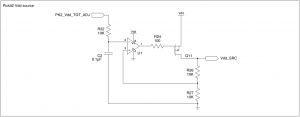
Pickit2 Vdd buffer

PICkit 2 Vdd buffer

A PWM output[3] (PK2_Vdd_TGT_ADJ) is used as a rough DAC by passing it through an RC lowpass (R22 and C2), resulting in a steady analog level. The op amp is configured to double the input, so the DAC must output half of the intended voltage. The PFET in the feedback loop increases the current capacity of the amp output.

The maximum target Vdd is less than the programmer’s Vdd due to drops that exist within the programmer. One workaround is to make the target self-powered; all of the lines are set up such that even a 6V target shouldn’t harm a programmer running at 3.3V[4]. By self-powering like this (with any programmer), it becomes more difficult to enter program mode with some targets: The timing requirements vary from device to device, but several of them require Vpp to rise a very short time[5] after Vdd initially rises. When the target is self-powered, ICSP_Vdd cannot be driven low by the programmer. There might be some secret to making this work that I just haven’t read yet.

It would also work to patch in a higher voltage (maybe 6-7V) to the source of the PFET instead of Vdd. For an actual PICkit 2, this would involve some messy hacking that would more likely ruin the device than improve it.

My own ideas

I’ve been toying with an idea to make a production-capable (or nearly-production-capable) programmer based on the principles of these designs plus some of my own ideas.

  • Arduino implementation.
    • This is partly because I think it’s funny, but mostly because it caters to impatience: If you suddenly need a PIC programmer, nobody sells a PICkit retail but at least RadioShack and Fry’s have some variation of Arduino for sale.
  • Full support for any combination of 3.3V or 5V programmer and target.
    • Some Arduinos and other development boards are pushing for 3.3V logic. I say, sure, why not?
  • Push-pull switching for Vpp and Vdd.
    • I think the Vpp switch on PICkit 2 would be a good model for both Vpp and Vdd. I don’t dislike MOSFETs, but I have a zillion PNP and NPN devices and only a very small number of FETs.
    • Using the PK2 Vpp switch for Vdd would allow use of e.g. 5V target with 3.3V programmer. Q2 and Q3 serve as a sort of level shifter.
  • Full level shifting for I/O lines.
    • A level shifter I’ve been playing with in a simulator[6] starts with a buffered 1V supply (2 silicon diodes, 1 Schottky diode, 1 NPN, and input voltage of 2V or higher) through 470 ohms to the base of an NPN. The input is the emitter of that transistor, and the output is the collector, which is pulled up to the desired output voltage.
    • A bidirectional variation of this[7] is to use 2 NPNs with the bases tied together (to the same 1V through 470 ohms) and cross couple each collector to the other emitter, finally pulling up each side to the desired voltage.
      • Unlike the common 1-NFET bidirectional shifter, this design does not require the advance knowledge of which side will be higher, so the target is allowed to be either higher or lower than the programmer.
    • Since these shifters pull up rather than down, firmware or other circuitry expecting pull-down behavior would need to be adapted.
  1. [1]Several are listed, the simplest being a 13V linear regulator based on an adjusted 7812.
  2. [2]Configured to 150kHz.
  3. [3]Again, configured to 150kHz.
  4. [4]But don’t quote me on that.
  5. [5]Less than a small number of ms
  6. [6]Not an original creation.
  7. [7]Also not an original creation.

On Facebook, I recently posted the following:

Inspiration of the moment: I hate voicemail. If I don’t have an opportunity to chat right away, a voicemail is every bit as inconvenient. So my idea is this: Record a message whose first five seconds are “please email or leave a text instead of voicemail” and whose remaining 25 seconds are an unlistenable cacophony of screeching, blaring noise. That would at least keep it down to machines and the ultra-dedicated.

This got a few Likes, so I decided to start working on something. Attached to this post is a tame first draft of the voicemail message. It doesn’t include the 25-second ear horror (which I’d like to make later to test any skills I may have as a cacophonist), but does have a creepy voice[1] telling human listeners to leave a text or send an e-mail instead and to “please hang up”, plus error tones[2] to confuse some machines and repetition to discourage humans from waiting for the actual record tone.

Use at your leisure (and, of course, your own risk) and do share stories of any good (or bad) results.

Download

  1. [1]“Tom”, a text-to-speech voice whose unsettlingness partly comes from its use in NOAA weather radio and some areas’ Emergency Alert System notices.
  2. [2]Specifically, Special Information Tones (SIT) such as those used by TeleZapper that indicate to some kinds of auto-call machinery that the line has been disconnected.

(ANTLR users searching for an answer, you might skip the prose and head to the listings. They’re meant to be readable outside full context.)

What follows is a toy grammar, a gross oversimplification of one I’ve been working on, used to explore a fairly simple but rather underdocumented possibility in ANTLR: Having a single lexer rule emit multiple tokens (or zero tokens, or an altogether different token than specified by the rule).

Synopsis

This language is called “SomeSx”, and it consists of dumbed-down S-expressions with a special “sigil” modifier, as follows:

  • A document consists of zero or more elements delimited by whitespace.
  • An element is an atom, a list, or a sigiled item.
  • An atom is an unquoted string of letters and digits.
  • A list is zero or more elements delimited by whitespace, surrounded by ( and ).
  • A sigiled item is a $that is either
    • followed directly by an element (with no whitespace between), which is then its topic, or
    • not followed directly by an element, in which case it has a special empty topic.

One might think of a sigiled item as one that represents either a nullary (if the topic is empty) or unary (otherwise) function. The source

alpha $bravo $ (charlie $() delta $(echo foxtrot) golf $) $

might transliterate, as an example, to the following JavaScript-like expression:

top(
	"alpha",
	$("bravo"),
	$(),
	[
		"charlie",
		$([]), // Note: not the same as empty topic
		"delta",
		$(["echo", "foxtrot"]),
		"golf",
		$()
	],
	$()
)

Parser

The parser grammar is straightforward enough. (I nerfed the ever-loving stuffing out of it to make it that way.)

// Parser

start : elementsOpt ;

elementsOpt : element* ;

element : atom | list | sigiled ;

atom : Atom ;

list : Down elementsOpt Up ;

sigiled : Sigil sigilTopic ;

sigilTopic : element | emptyTopic ;

emptyTopic : EmptyMarker ;

Do note how sigiled is matched: There’s always a Sigil token and then a topic. That topic is either a normal element or some special EmptyMarker to indicate that there is no topic.

This is the problem, of course: In the language described above, the fact that a topic is empty doesn’t correspond to a token but to what regexp fiends would call a zero-width assertion. Before we get to why that’s a problem, I’ll sidestep it for a moment by presenting a lexer for a slightly broken version of the language.

Lexer, makeshift/broken demo version

Imagine that the language described above, instead of determining an empty topic by detecting that whatever follows a sigil is not an element, just has an explicit empty topic token ~. The above input sample would then be written

alpha $bravo $~ (charlie $() delta $(echo foxtrot) golf $~) $~

which is easy to write a lexer for:

// Lexer, with explicit empty token marker

Space :
	( ' '
	| '\t'
	| '\r'
	| '\n'
	) {$channel=HIDDEN;}
	;

fragment Dollar : '$' ;

Down : '(' ;
Up : ')' ;
Atom : ('a'..'z'|'A'..'Z'|'0'..'9'|'_')+ ;

EmptyMarker : '~' ;

Sigil : Dollar ;

This works delightfully; alas, it doesn’t lex the language as specified. No, for that to happen, EmptyMarker would have to match not ~ but the empty string (a big no-no for any eventually deterministic lexer), and to only match it in well defined places.

One way to make a lexer rule in ANTLR that matches in exactly this way is to make it a fragment; we could use a syntactic predicate to cause the zero-width token to match only if whatever follows the sigil doesn’t look like the start of an element. It’s actually very easy.

Or not. The rule’s fragment-ness is a double-edged sword in this regard: Matching it does not emit any sort of token that can be used by the parser. Therefore, we’ll have to convince the lexer rule containing the fragment to emit it alongside any token it might have produced anyway.

And it can be done. There’s just some plumbing to do first.

Lexer support for arbitrary numbers of tokens per rule

Little aside. (And again, do skip it if you’re in a hurry. It’s hypocritical; I’m providing unnecessary information into an article I wrote out of frustration with information overload.)

Emitting arbitrary numbers of tokens from a lexer rule is actually a well-known problem in the ANTLR world, if not only because Python is so popular. In that language, the braces one would see in a C-like language are eschewed in favor of indentation changes. While that’s nice for the user (ymmv), it’s tricky for the lexer, which has to be able to spit out all sorts of made-up “indent” and “dedent” tokens resulting from monitoring the indentation state.

After running into much information overload on the subject, I flipped open my dead wood copy of The Definitive ANTLR Reference and found this gem around pages 110-111:

Note that, for efficiency reasons, the CommonTokenStream class does not support multiple token emissions for the same invocation of nextToken(). Read the following from class Lexer when you try to implement multiple token emission:

When I read this, I truly had to fight the urge to throw the tome hard across the room. ANTLR’s finest documentation, lovingly crafted by the creator, is unfortunately (but justifiably) not free information. I have the thing itself in my hands, and it not only tells me that I’m going to have to override some methods to get it to work the way I want, but then has the nerve not to offer a concrete implementation and that I’m just going to have to “try to implement” it.

Additionally, a comment in the code snippet offers this:

Currently does not support multiple emits per nextToken invocation for efficiency reasons.

It might not need to be default, but I’d think this is a common enough thing that it might be simple (and more descriptive and easier to carry across target platforms) to have some settable flag for multiple emit support rather than requiring ugly ad hoc overrides.

Of course, this was at the end of a night of fruitless searching for an answer, and it’s a wonder nobody was killed.

Fortunately for humanity itself, I was finally able to extract the core nugget of knowledge from a wiki page that had quite a bit of unrelated (to me, anyway) surrounding information hiding it from plain sight.

Near the end of the text itself was the treasure: The overrides for emit(Token) and nextToken() that I needed. Sadly, it was for an earlier version of Java and of ANTLR, but I was able to port code from a more recent post by a user of the C# target.

Without further ado, the very simple guts of a multi-emitting lexer, for Java 1.6 and ANTLR 3.4:

// Without this code, or something similar, lexer rules emitting multiple
// tokens will not work correctly. (Try it if you don't believe me.)

@lexer::header {
	import java.util.Deque;
}
 
@lexer::members {
	// Substitute any compliant Deque implementation to taste
	Deque<Token> tokens = new java.util.ArrayDeque<Token>();
	
	@Override
	public void emit(Token token) {
		state.token = token;
		tokens.addLast(token);
	}

	@Override
	public Token nextToken() {
		super.nextToken();
		if (tokens.isEmpty())
			return Token.EOF_TOKEN;
		return tokens.removeFirst();
	}
}

Modifying the lexer to produce the marker token on cue

Here, we just follow through with the modification ideas from earlier: Have the Sigil token perform as before if, and only if, it detects that it is immediately followed by an element. If not, have it match a zero-width fragment token, then emit the Sigil followed by the EmptyMarker tokens. The details are provided inline:

// Lexer changes for implicit empty topic

// EmptyMarker is changed to match a zero-length string. In ANTLR (at least), a
// zero-width lexer rule is practically useless (it could match anywhere, and
// it's unclear where it's supposed to) unless it is a fragment. As a fragment,
// it matches exactly where we put it. But as a fragment, it doesn't emit a
// token...without some effort (read on).
fragment EmptyMarker : ;

// This fragment reflects the beginning of any explicit sigil topic: the first
// token in an atom, list, or sigiled. Used in a syntactic predicate, we can
// determine whether a token we're matching is followed by an explicit,
// non-empty topic.
fragment StartOfNonEmptyTopic : Down | Atom | Sigil ;

Sigil : d=Dollar
	// The Sigil token is changed to do what it did before as long as the token
	// appears immediately before what looks like a non-empty topic. 
	( (StartOfNonEmptyTopic)=> // already does the right thing; add nothing.
	
	// But if no such token follows, we have to output the sigil (as normal)
	// but then also insert a zero-width EmptyMarker afterward.
	| z=EmptyMarker // not followed by explicit topic; insert an empty one
		{
			// The tokens are fairly fluid; several of their properties can be
			// changed at will. In this case, the type of a token can be
			// changed while retaining its text content, line and column
			// numbers, and so forth.
			
			// From what I can tell, using emit(Token) directly will prevent
			// any token being emitted by the rule itself. So, if you use it
			// once for a fake token, be prepared to use it for the real one as
			// well.
			
			$d.setType(Sigil);
			emit($d);
			
			// You might have noticed that $z is already a EmptyMarker. Why set
			// the type? From looking at the generated lexer code, it appears
			// that a matched *fragment* rule creates a token with not the
			// named type but an unmatchable dummy token type. However, the
			// fragment token type (or any other token type) can be stuck back
			// onto it to make it work.
			$z.setType(EmptyMarker);
			emit($z);
		}
	)
	;

Peripheral caveats

Mostly not specific to this issue, but in general for ANTLR: Mind your generated code. Lots of stuff that might be wrong with your lexer will produce useless, misleading, or even absent diagnostic information. It’s not your fault, and fixing it might only require some changes in convention. For example:

  • I think I’m going to stick with CamelCase lexer rules, if only because ANTLR itself reserves a few all-caps ones such as DOWN and UP.
  • The aforementioned wiki page contains the phrase d=DIGITS r='..'; when I tried to match the dollar sign as a quoted string (i.e. d='$') the resulting variable in the generated lexer was an int rather than a Token. If you were curious why Dollar is its own fragment, this is the reason. (Perhaps double quotes would have worked—it wasn’t the first thing I tried, so I didn’t.)

Finally, I have to make sure to meditate and do my best not to be quick to anger toward Terence Parr et al. Language makes for really, really difficult computational problems, and despite the vast collection of warts in JARs, I do think ANTLR really is the best we’ve got, and I hate to consider the needless loss of life were I to attempt much of what I try to do with flex and bison.

The whole thing

Here is how everything fits together. Most comments have been removed to drive home how simple this whole thing is really supposed to be.

grammar SomeSx;

@lexer::header {
	import java.util.Deque;
}
 
@lexer::members {
	Deque<Token> tokens = new java.util.ArrayDeque<Token>();
	
	@Override
	public void emit(Token token) {
		state.token = token;
		tokens.addLast(token);
	}

	@Override
	public Token nextToken() {
		super.nextToken();
		if (tokens.isEmpty())
			return Token.EOF_TOKEN;
		return tokens.removeFirst();
	}
}


// Parser

start : elementsOpt ;

elementsOpt : element* ;

element : atom | list | sigiled ;

atom : Atom ;

list : Down elementsOpt Up ;

sigiled : Sigil sigilTopic ;

sigilTopic : element | emptyTopic ;

emptyTopic : EmptyMarker ;


// Lexer

Space :
	( ' '
	| '\t'
	| '\r'
	| '\n'
	) {$channel=HIDDEN;}
	;

fragment Dollar : '$' ;

Down : '(' ;
Up : ')' ;
Atom : ('a'..'z'|'A'..'Z'|'0'..'9'|'_')+ ;

fragment EmptyMarker : ;

fragment StartOfNonEmptyTopic : Down | Atom | Sigil ;

Sigil : d=Dollar
	( (StartOfNonEmptyTopic)=> // normal
	| z=EmptyMarker // insert empty token
		{
			$d.setType(Sigil);
			emit($d);
			
			$z.setType(EmptyMarker);
			emit($z);
		}
	)
	;
A rule known as the fundamental theorem of arithmetic states, in so many words, that any natural number is uniquely representable as a multiset of prime factors, and vice versa. Having two operands in this form makes some operations easier and other ones more difficult.

This discussion assumes certain definitions of terminology:

  • natural number : A positive integer; an integer 1 or greater.
  • prime number : A natural number with exactly two distinct natural factors, 1 and itself. In particular, 2 satisfies this requirement despite being even, while 1 does not satisfy this requirement because it has only one such factor instead of the required two.
  • multiset : A generalization of a set wherein the multiplicity of each item is significant.

The natural number indicated by a given multiset is the product of 1 and each element of the multiset. For example, 1 is represented by the empty multiset {∅}, 3 by {3}, 5 by {5}, 15 by {3,5}, 25 by {5,5}, and so on.

Multiset operations on the multisets correspond to other operations on the natural numbers they represent:

  • Intersection (i.e. retaining the lesser multiplicity per element) is equivalent to finding the greatest common divisor (gcd):
    • gcd(54, 24)
    • {2, 3, 3, 3} ⋂ {2, 2, 2, 3}
    • {2, 3}
    • 6
  • Union (i.e. retaining the greater multiplicity per element) is equivalent to finding the least common multiple (lcm):
    • lcm(8, 12)
    • {2, 2, 2} ∪ {2, 2, 3}
    • {2, 2, 2, 3}
    • 24
  • Addition of the multiset (i.e. retaining the sum of multiplicities per element) is equivalent to multiplication:
    • 414 * 555
    • {2, 3, 3, 23} + {3, 5, 37}
    • {2, 3, 3, 3, 5, 23, 37}
    • 229770
  • Subtraction of the multiset (i.e. retaining the differences of multiplicities per element between one set and another) is equivalent to division:
    • 88088 / 2002
    • {2, 2, 2, 7, 11, 11, 13} − {2, 7, 11, 13}
    • {2, 2, 11}
    • 44
    • Note that this division is not closed on natural numbers unless the result would also be a natural number (i.e. the left operand must be divisible by the right) because the multiset subtraction itself is not closed on multisets (with nonnegative multiplicities). The multiset notation can still help to reduce the fraction to lowest terms:
      • 2310 / 273
      • {2, 3, 5, 7, 11} − {3, 7, 13}
      • {2, 5, 11} − {13} (since the multiset can’t have negative multiplicities, this is the simplest form)
      • 110 / 13
  • Multiplying all of the multiplicities in the set by n yields the number to the nth power:
    • 1684
    • {2, 2, 2, 3, 7} multiplicities multiplied by 4
    • {2, 2, 2, 2, 2, 2, 2, 2, 2, 2, 2, 2, 3, 3, 3, 3, 7, 7, 7, 7}
    • 796594176
  • If all of the multiplicities in the set are themselves divisible by n, dividing them yields the nth root of the number:
    • ∛474552
    • {2, 2, 2, 3, 3, 3, 13, 13, 13} multiplicities divided by 3
    • {2, 3, 13}
    • 78
  • Meanwhile, the natural-to-multiset transform won’t help you at all with addition and subtraction.

Almost as fun as it looks.

Print your own, if you’d like!

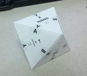
This octahedral toy/tool/thing represents manipulations on a logic gate with two inputs A and B and one output Y. A face of the object says what operation it executes, such as “AND”. From there, each side of the face is marked with a variable—A, B, or Y—and rotating past that edge shows you the result of inverting that variable.

For example, if I start at AND, I might turn past Y to NAND (AND with inverted output). Then, I might turn past A to IF (another name for OR NOT), because that’s what /A NAND B is. Finally, I might turn past B to OR, since that’s A OR NOT /B.

Alternatively, you might choose a starting point and an ending point, then trace the path between them to determine how many inverters are necessary to do the conversion.

Note that any face is at most three turns from any other. Polar opposites such as AND and OR are on opposite faces, and changing one to the other involves inverting each input and the output.

The somewhat uncommon logical operator names IMP (short for IMPLIES), NIMP, IF, and NIF appear as one-word substitutes for operations that invert B (NAND NOT, AND NOT, OR NOT, and NOR NOT, respectively). The two-word versions appear as a subtitle.

This isn’t quite as great as it could be. The text sizes and layout need a lot of work; the expression text is only barely big enough to read. However, since the time may never come for improvement, here it is for you to play with.

Enjoy!

Yesterday’s post got me thinking way too hard about the ubiquitous 555 timer. Specifically, I wondered if I might have been missing an optimization that would knock out one of the 555s necessary to make the transparent latch. It turns out that I was right, provided that an active-low enable line is doable. (Details follow.)

Skip this bit if analog creeps you out: The 555 timer has some analog circuitry that seems to be used in the majority of its applications. There is a control voltage (CV) pin that sets thresholds for comparators at the TH (threshold) and /TR (trigger) pins. If TH is above CV, then it registers as high (low otherwise); if /TR is below CV/2, then it registers as low (high otherwise). CV can be set externally[1], but usually it’s left alone, and its default setting is CV = 2Vcc/3 (making CV/2 = Vcc/3).

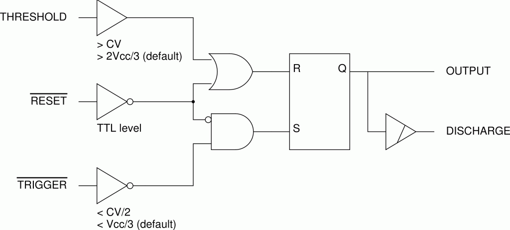
Really, that’s where the analog part ends. The rest is basically digital, and digital is far more comfortable for those of us from the computer side of the house. The 555 timer is basically an RS latch with mildly analog inputs, plus a preemptive additional reset (/RST). I realized that’s still vague for my taste, so I scribbled out a bunch of notes, drew up some tables, and eventually came up with the following logical equivalent of the 555:

Even if you ignore for a moment the tweakable threshold voltage settings on the threshold and trigger inputs, the 555 has interesting possibilities as a digital circuit.

(Edit: A demonstration of the above on Falstad.)

The chip has three logical inputs. One, /RST, is a legitimate TTL input that is inverted. The others feed into comparators as just described, but ignoring the level details, TH simply feeds into a buffer and /TR pin feeds into an inverter. There are also two outputs, OUT (output) and DIS (discharge) pin. Both carry the same data, but OUT is driven as a logic level while DIS is open-collector[2].

If you ignore the /RST, the 555 is an R-/S latch, where TH and /TR pins serve as R and /S, respectively. If both of those signals are active, the result is by definition undefined.

/RST adds to this an overriding additional reset signal. When active, the output is defined as low even if /TRis also active.

By extracting the behavior of a plain RS latch from this, the relationship among the inputs is clarified:

  • The latch is set if /TR is low and /RSTis high.
  • The latch is reset if THis high, /RSTis low, or both.

Some degenerate cases:

  • As noted before, if /RST is high then TH and /TR form an R-/S latch.
  • If TH is low, then /RST and /TR form a kind of R latch[3], with /RST and /TR as /R and /S, respectively.
  • If TH and /TR are tied together as a single input, and /RST is used as another input, the result is an “AND NOT” logic gate, with TH+/TR as the inverting input and /RST as the non-inverting input.
    • The inverting input is effectively Schmitt-triggered, with the hysteresis zone set between CV/2 and CV. (/RST remains a normal TTL input.)
    • With /RST tied high, this becomes a Schmitt-triggered inverter.

Of particular interest is the R latch. This particular latch is set when /TR is low and /RST is high. On the other hand, this latch is reset when /RST is low with no other condition. When I saw this it seemed a bit familiar, like /RST being high enables the value of /TR having any impact.

So, I prepared a truth table for the D and E lines of a D latch, and entered the corresponding values of /R and /S. The result: /S = /E, and /R = D or /E.

My first conclusion is that, if you’re not bound to using only 555 elements, this could make things a lot easier. It requires an active-low /E, if that can’t be accomplished anywhere else, an NPN inverter (one transistor, two resistors) will suffice. /E is fed directly into /S, and a diode-logic OR gate (2 Schottky diodes, one resistor) figures /R. Even with the inverter that’s way fewer parts than yesterday’s solution.

In four parts, a D latch with active-low enable. Slap an inverter (also pictured) onto the front to make it a normal enable.

(Edit: A demonstration of the above on Falstad.)

Translating the setup to all 555s is trickier. If you can set up for active-low both /E and /D, it’s possible to get it down to three elements: The latch, an inverter into /R, and an AND NOT gate. This follows from the proposition that R = /D and E = /D and not /E. Then, /R = not R. And, of course, for active-high D you add an inverter—4 elements, no better than yesterday.

The difficulty is that the only gate a single 555 can simulate (other than an inverter) is an AND NOT. While it’s possible to make any other gate from AND NOT parts, some take more fudging than others. To make the OR gate we’d like, you need three. My derivation[4] is as follows:

  • A OR B
  • NOT (A NOR B)
  • NOT ((NOT A) AND NOT B)
  • NOT ((1 AND NOT A) AND NOT B)
  • 1 AND NOT ((1 AND NOT A) AND NOT B)

Note that in the last stage there are three “AND NOT”s and no other operators. Note also that, using (Schottky) diode logic, the parts count is the same: Two diodes and one resistor. Guess which one I’d rather breadboard.

  1. [1]Its default value comes from a resistive divider of approximately 5K vs. 10K, so if the value is critical it’s probably better to set it via a lower impedance, such as with a voltage reference or a (unity gain) buffer.
  2. [2]0V on low, high-impedance on high.
  3. [3]An RS latch that favors R in a tie
  4. [4]Through repeated application of DeMorgan’s laws.

Younger hobbyists who want to do arithmetic in an electronics application may think that a microcontroller is the only way to do it. I present something far more old-school.

image

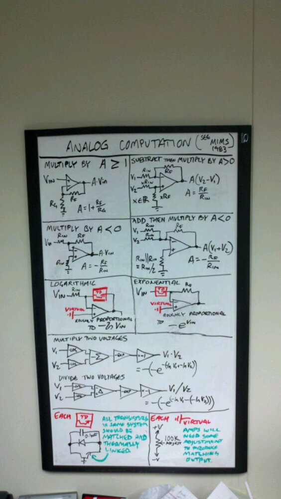
How to do simple math on real numbers in a very non-digital way.

If you can represent the scalar terms of an arithmetic expression as voltages and/or resistances, then many operations can be performed with op amps (which is, incidentally, what the “op” part means). Several of the major features are described above.

  • The word “amp”, for amplifier, refers to the fact that the device amplifies, or enlarges, an input signal by a factor called gain which is represented by the letter A[1] When A is fixed, the amplifier serves to multiply the input signal by A. By default, A is ideally infinite[2], but can be set to a fixed value using resistors.
  • Division (not pictured) can be performed using a resistor divider network. No op amp is required, though using one might be desirable to avoid loading effects.
  • “Subtract then multiply by A > 0″: An op amp’s natural mode (in my opinion, anyway) is the differential amplifier. Two voltages are input; V2 is subtracted from V1, and then the difference is multiplied by A, which is based on the ratios of resistors used. All other linear modes pictured can be described in terms of this one:
    • “Multiply by A >= 1″: If you take the divider off of V2 and replace it with Vin, it’s equivalent to setting V2 to Vin(1 + Rin/RF). Then, just set V1 to 0. The result is A(V2V1) = (RF/Rin)Vin(1 + Rin/RF) = Vin(1 + RF/Rin).
    • “Multiply by A < 0″: Let V2 = 0, V1 = Vin. The result is A(V2V1) = (RF/Rin)(0 – Vin) = Vin(-RF/Rin).
    • “Add then multiply by A < 0″: Exactly the same as the previous case, except that the input is from a resistor divider network. If V1 and V2 are fed to the same point through equal resistances as shown, it’s equivalent to a single input of VX = (V1 + V2)/2 through a resistance of RX = Rin/2. With the other input at 0, the result is A(0 – VX) = (RF/RX)(-VX) = -(2RF/Rin)((V1 + V2)/2) = -(RF/Rin)(V1 + V2).
  • “Logarithmic” and “Exponential”: An NPN transistor with a grounded base can be placed either at the feedback or the input to implement a logarithmic or exponential output, respectively. The coefficients of the expression are not well defined, since they vary from instance to instance, but if the transistors used are closely matched and thermally linked (for example, in a single-chip transistor array) then with some tuning their outputs will be consistent. A log transform can be used to easily multiply (by adding logarithms) or divide (by subtracting logarithms) two voltages.
  • Comparison (not pictured): As discussed here previously, a comparator is a sort of op amp specialized to output only logical high/low depending on whether the value at the non-inverting input is higher than the value of the inverting input, outputting high and low, respectively. In a pinch, an op amp will do the same thing in the open-loop configuration—direct inputs and no feedback, resulting in the extremely high gain mentioned earlier. If the non-inverting input is even slightly different than the inverting input, that small difference is amplified so immensely that the output will be either the highest possible or the lowest possible, meaning around the positive and negative supply voltages, respectively. Use of an actual comparator is preferred though, since it is better tuned for digital use.
  1. [1]The “A” presumably refers to “amplification”.
  2. [2]But in practice is just a very high number.