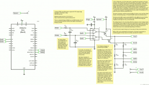
Concept: 2-channel PWM-controlled power output

If it works as intended, this circuit should allow an Arduino to control 2 different output voltages via PWM.
(EDIT: The above is the second revision.[1] Note also that the above will not work as-is, except perhaps in the NPN or N-channel variants; it doesn’t account for the fact that the op amp outputs peak well below the voltage necessary to turn off a PNP or P-channel transistor.)
Out of nowhere I just happened to find an 18V wall wart in my junk box. The lack of such a thing makes it necessary for a PIC programmer to produce its 12-14V programming voltage some other way, such as with an adjustable regulator and a pair of 9V batteries or with a boost converter. Even so, a programmer for production-quality output must be able to adjust its own programming voltage as well as its own output supply voltage.
The schematic pictured here is for a 2-channel PWM-adjusted power output. Each channel starts with a lowpass filter, which coerces a PWM signal to its equivalent analog voltage level. This level is the reference for an error amplifier, where feedback from the output is compared with it. The amplifier controls a pass transistor that then drives the output load. Finally, feedback from the output is read by an ADC so that the firmware can make adjustments to the PWM duty cycle.
Note that “feedback from the output” appeared twice just now, once for the error amplifier and again for the ADC. These are both proportional to the output voltage, but with different proportions. This could be trivially done with two voltage dividers, but in this schematic both feedback voltages come from different points on a three-resistor ladder, saving one resistor.
I haven’t tested this yet, but it’s on the breadboard and ready to test. For this, I have Fritzing to thank. It’s quirky and not super-easy, but that can be said of any EDA software.
- [1]This version uses P-channel MOSFETs instead of PNP, and better explains the power requirements.↩