Analog Computation
Younger hobbyists who want to do arithmetic in an electronics application may think that a microcontroller is the only way to do it. I present something far more old-school.
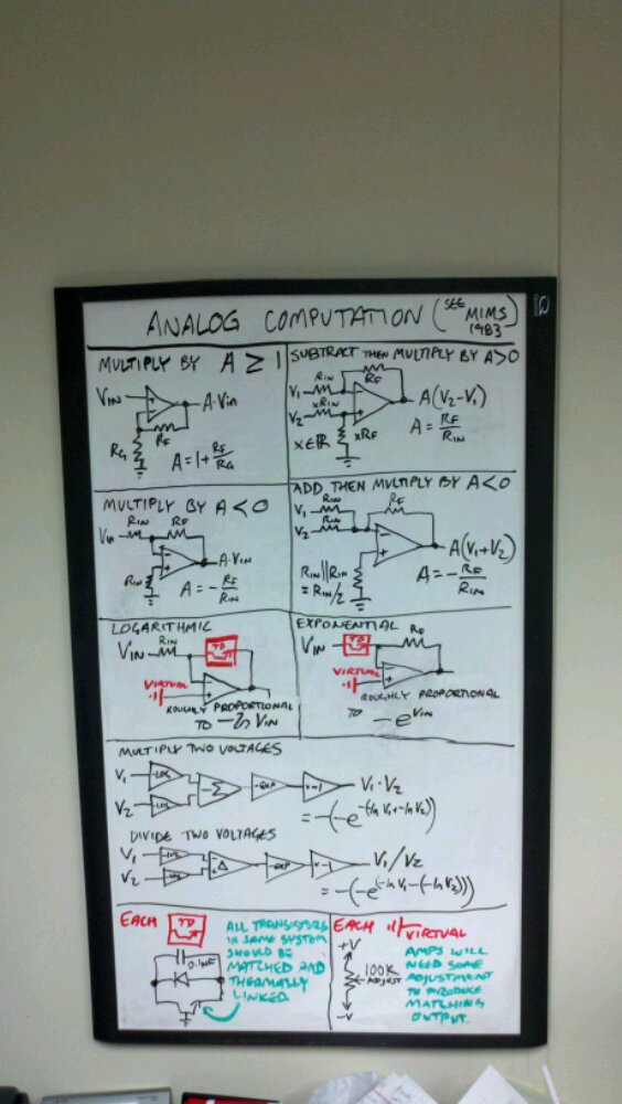
How to do simple math on real numbers in a very non-digital way.
If you can represent the scalar terms of an arithmetic expression as voltages and/or resistances, then many operations can be performed with op amps (which is, incidentally, what the “op” part means). Several of the major features are described above.
- The word “amp”, for amplifier, refers to the fact that the device amplifies, or enlarges, an input signal by a factor called gain which is represented by the letter A[1] When A is fixed, the amplifier serves to multiply the input signal by A. By default, A is ideally infinite[2], but can be set to a fixed value using resistors.
- Division (not pictured) can be performed using a resistor divider network. No op amp is required, though using one might be desirable to avoid loading effects.
- “Subtract then multiply by A > 0″: An op amp’s natural mode (in my opinion, anyway) is the differential amplifier. Two voltages are input; V2 is subtracted from V1, and then the difference is multiplied by A, which is based on the ratios of resistors used. All other linear modes pictured can be described in terms of this one:
- “Multiply by A >= 1″: If you take the divider off of V2 and replace it with Vin, it’s equivalent to setting V2 to Vin(1 + Rin/RF). Then, just set V1 to 0. The result is A(V2 – V1) = (RF/Rin)Vin(1 + Rin/RF) = Vin(1 + RF/Rin).
- “Multiply by A < 0″: Let V2 = 0, V1 = Vin. The result is A(V2 – V1) = (RF/Rin)(0 – Vin) = Vin(-RF/Rin).
- “Add then multiply by A < 0″: Exactly the same as the previous case, except that the input is from a resistor divider network. If V1 and V2 are fed to the same point through equal resistances as shown, it’s equivalent to a single input of VX = (V1 + V2)/2 through a resistance of RX = Rin/2. With the other input at 0, the result is A(0 – VX) = (RF/RX)(-VX) = -(2RF/Rin)((V1 + V2)/2) = -(RF/Rin)(V1 + V2).
- “Logarithmic” and “Exponential”: An NPN transistor with a grounded base can be placed either at the feedback or the input to implement a logarithmic or exponential output, respectively. The coefficients of the expression are not well defined, since they vary from instance to instance, but if the transistors used are closely matched and thermally linked (for example, in a single-chip transistor array) then with some tuning their outputs will be consistent. A log transform can be used to easily multiply (by adding logarithms) or divide (by subtracting logarithms) two voltages.
- Comparison (not pictured): As discussed here previously, a comparator is a sort of op amp specialized to output only logical high/low depending on whether the value at the non-inverting input is higher than the value of the inverting input, outputting high and low, respectively. In a pinch, an op amp will do the same thing in the open-loop configuration—direct inputs and no feedback, resulting in the extremely high gain mentioned earlier. If the non-inverting input is even slightly different than the inverting input, that small difference is amplified so immensely that the output will be either the highest possible or the lowest possible, meaning around the positive and negative supply voltages, respectively. Use of an actual comparator is preferred though, since it is better tuned for digital use.