Archive

Concept

[Strong Bad’s e-mail has undergone a tremendous Interface Screw, and the screen on his computer has literally drained all of its content onto the floor.]
Homestar: Never fear, Strong Bad! I know how to fix your computer box.
Strong Bad: No, no, don’t touch that!
Homestar: Your super box needs words.
sbemail 118

While cleaning up for an event at my house yesterday, I happened upon the lifeless husk of a DVD player that was ruined by a lightning strike just over a year ago.

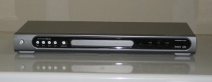
This was once a DVD player.

Today being my day off, I took it apart just to see what might be salvageable. Granted, the defibrillation it took probably derated most or all of its electronic components, but perhaps some of the switches and connectors came through intact. While I was taking it apart, it occurred to me that its most attractive feature would have been untouched by the strike: Its case. On the front, it has a panel of six tactile buttons on a breakout board (if they were damaged, they’re a common style that’s easily replaced), three optic pipes on the right for PCB-mounted status LEDs, a transparent area for an IR receiver, and the tray door, which is spring-biased closed by default. On the back, there is a place for a power cord and an array of analog AV connectors (RCA and S-video). And, of course, the form factor is worth noting: It’s the size and shape of a DVD player, and as such would be a good fit for a set-top box.

Now, what could I put in that box to make it useful? One possibility would be the vastly underused Acer Aspire One I bought two and a half years ago.

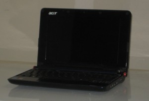
As the name suggests, this computer aspires to be used on a regular basis.

This computer has served me nicely on a few rare occasions that I’ve needed a computer without expecting to. However, it would have been a better fit for my previous life in DC, and most uses I had for it have fallen onto the Droid I started carrying for work. It’s no powerhouse; you’d be hard-pressed to run any particularly impressive graphics on it, or even complex Flash movies. But it runs Ubuntu, it can do YouTube, it’s adequate with emulators, and it can reportedly even run MythTV (think tinkerer-friendly TiVo). As far as I know, it doesn’t have TV in or out, but it has a DE-15F VGA connector, and my current TV (which replaced a TV that was zapped in the aforementioned incident) happens to have VGA in. Nice. The computer is easy on both power and ventilation requirements, and, well, it’s a netbook—the guts are small enough to be mounted in a wide variety of alternative cases.

This being an interesting place to have a computer, it would have to have a variety of interesting interfaces. The Acer already does wi-fi, and that’s a very good start. There’s a place for a IR receiver, and that would definitely be a must; LIRC would be the jumping-off point there.

Aside from that, you may have noticed that I’ve been writing a lot lately about game controller interfaces. I’ve been turning over in my head the possibility of a DE-9M gameport that is electrically compatible with controllers for Sega (Genesis), Nintendo (NES, SNES, N64, GameCube), and Sony (PS, PS2), with firmware extensible to more designs as necessary. It would be possible to connect a Sega controller directly; all of the others would utilize an almost-passive[1] adapter. DE-9 connectors are compact (most of the aforementioned controller connectors are huge by comparison) and very easy to source and replace.

Using a single connector on the console end instead of a smattering[2] simplifies the wiring and the board design while offloading the hairy details to external adapters. This last point is important because it’s tricky to find many controller connectors in panel-mount forms[3], but extension cables are common as accessories, usually not as tricky to source.

So, folks, interesting possibilities!

  1. [1]Adapters for non-Sega controllers would contain circuitry to identify which alternate configuration it should use, probably as simple as a transistor and two resistors totaling less than a quarter in parts.
  2. [2]The RetroN 3 takes this approach, with two ports and a cartridge slot each for three different systems.
  3. [3]I’ve actually made panel-mount PS controller ports using extension cables, metal L-shapes, and a generous application of epoxy. Didn’t turn out too badly, either.

A hard truth that I think everyone who makes stuff has to come to terms with is that it’s basically impossible to do everything one wants to do within a lifetime. The proportion of imagination (the plans) to wherewithal (the means) has got to be at least exponential. (Perhaps that’s for the best.)

In other words, my time and resources have never really been able to keep up with my ideas. At any given time, unless I’m worn out or recuperating from something, I can expect to have several new ideas in the hopper before I’ve finished the one I’m already on. This doesn’t end well. Some of the time I can actually slog my way through to the end of what I’m working on, generally at the expense of the exciting new ideas. More frequently, however, I end up with another project at 30 to 50 percent completion. I think I inherited this from my dad. He was a very smart and inventive guy, and my childhood was practically littered with impressive projects started by him and then preempted by life.

Anyway, my angle here is that I have ideas that I like but am not currently working on. I offer a sampling [Edit: See Back Burner for an up-to-date version of this list.]:

  • Arcade-style dance machine. Summarily, a StepMania/DDR cabinet with custom input and output interfaces. This was my timesink around 3 or 4 years ago. I invented a special soft-touch sensor square that offers a bit of shock absorption and has LEDs embedded in the top of the panel. I created an RS-232 interface for animating LEDs. I was even working on convincing an 18F PIC to identify itself to a computer as a USB gamepad so I’d have something better to deliver than a hacked-apart controller. I bought a used TV for the purpose.
  • A solid-state dual AC switch/dimmer with opto-isolated microcontroller input. This would be more or less a twin solid-state relay (SSR) with dimming capabilities. It could be used to make a computer turn on the marquee light of an arcade machine or act as a speed controller for a rotary tool. This circuit could easily be built into an outlet box with a pair of sockets. An application note by Fairchild (AN3003, PDF warning) has as figure 9 a very basic SSR that seems suitable. I’d be making one of these per outlet.
  • A knockoff of a Griffin PowerMate that isn’t made out of a scroll wheel. Basically, a rotary encoder with a hand-sized cap attached.
  • A really big rotary encoder wheel. Actually, that was part of the DDR machine concept. I bought and dismantled a pair of rollerblades from Goodwill to harvest their bearings. Those are also still waiting for my attention.
  • A RepRap. But who doesn’t want one?
    • Not to mention all sorts of creative apparatus, including a 3D plotter, CNC mill, CNC vinyl cutter, on down to a UV station for photoresist boards, but these are far more likely to be bought than made.

And I’m confident that I’m capable of making all of these things and many, many more, but not necessarily in the same lifetime.

Fortunately, I’m not presently in despair about this; it’s merely an irritation. It’s frustrating to know from the get-go that whatever I’m starting isn’t likely to come to a meaningful conclusion.

On the other hand, someone of the mindset that it’s not the destination but the journey would call this a victory—a life that’s all journey and no destination. Sometimes I can see it this way, also. :-)

Some of you may (and the rest of you won’t) remember a time in the history of your computer usage where starting up your machine took almost no time at all and the thing confirmed that it was “READY” to hear what you had to say. It would even give you a coherent response if you typed in a simple arithmetic expression (as long as you typed a “?” first). It was good stuff.

Atari 800XL startup screen

The Atari 800XL screen as it appeared the moment you turned the power on—in BASIC and awaiting your command. Few computers before or since have been this prepared.

Read More

In the previous post, I believe I dismissed Manchester coding too quickly as a possibility, thinking that some unwieldy analog circuitry would be necessary for its implementation. Today, I realized that it would actually be fairly easy to create a decoder using microcontroller code that would fairly easily handle arbitrary bitrates and even possibly do a decent job accounting for drift.

To explain, Manchester coding is a type of self-clocking signal (i.e., it combines data and clock lines) that guarantees either one or two edges (transitions from low to high or high to low) per bit. A logical 0 starts high and then switches to low mid-bit; a logical 1 goes low to high instead.(Described above is the IEEE version. As the image shows, it’s possible to flip the two by convention.)

What the microcontroller must do to make sense of such a signal is pretty simple, much to my delight. It’s simple because there are only two possibilities for the duration between transitions; we’ll call them D/2 for the narrow pulses and D for the wider ones. Assuming we have a decent guess at what D is (we’ll get to that), and that any two consecutive D widths are reasonably similar, we can decode the pulse train and even compensate for gradual drift of the D value. It goes something like this:

  • Say we have 3 initial guesses for D, which are D0, D1, and D2. At any given moment, our estimated value of D = (D0 + D1 + D2)/3.
  • At each transition, find X, the distance between this and the previous transitions.
    • If X < (3/4)D, consider X to be approximately D/2. Ignore this transition and start waiting for the next one.
      • If 4X < 3D then X < (3/4)D. 4X = X shifted left 2. 3D = D0 + D1 + D2. No actual multiplication or division required!
    • If (3/4)D ≤ X < (3/2)D, consider X to be approximately D. Accept the current input as the next bit. Let D0 = D1, D1 = D2, D2 = X.
      • If 2X < 3D then X < (3/2)D. 2X = X shifted left 1. 3D is as above.
    • If X ≥ (3/2), the transmission has ended or there is an error; handle accordingly.

Using this mechanism, the average of the previous three bit widths is used as the expected width for the next bit, but the next bit can be nearly 25% narrower or 50% wider and still be valid. Since this sliding window approach is used, the bitrate could generally vary by quite a lot as long as the change is gradual. Oversampling is key here—I imagine that the receiver should try to sample at least 6 times (wild guess) the expected bitrate.

How do we set up initial guesses for D? Here’s one proposition on how to make an explicit initial sync:

  • The initial guess for D would be very short, possibly shorter than any actual expected D.
  • When the line is idle, it is held low, and should be held low longer than the max nominal 2D specified by the system. Consequently, if the line is low for over twice the expected 2D, the receiver should recognize an idle state.
  • When a frame is about to be sent, the line goes high for exactly X = 2D as decided by the sender. At the next high-low transition, the receiver assigns D0 and D1 based on this value: D0 = X shift right 1; D1 = X – D0.
  • The transition following this transition is the start bit, which is a 1 (low-to-high). The width Y of the low before the transition is approximately D/2. Assign D2 based on this value: D2 = Y shift left 1.
  • Start sampling as specified from the start bit transition.
  • After some fixed number of bits, the frame ends with a stop bit, which is a 0 (high-to-low). After the bit, the line is held low to indicate idle as mentioned before.

This one’s got some true promise, I think. I’m guessing it may even be possible to get it working using a high-tolerance clock on the slave micro (such as an RC network) making it potentially feasible to use even a super-cheap one, like the PIC16F54 of which I happen to have plenty lying around, without an excessive amount of tuning. I could be wrong, though. Who knows?

Way back in 2007, I developed a big PC-controlled LED interface operated via serial port. The basic principle was simple: a PIC micro with a serial receiver pushed bits out to some shift registers which turned LEDs on and off.

The implementation was a bit more complicated:

  • A computer sends commands to the RS-232 port (nominally at 19200bps as I recall).
  • The serial line runs to a level converter (MAX232) that changes RS-232 signal voltages into TTL levels.
  • The converted signal runs into the serial port on a microcontroller (here the USART on a PIC16F88).
  • Code on the micro converts the received data into clock and data lines.
  • The signals from the micro are carried to the breakout board. (If the run is short enough, this part can be omitted entirely.)
    • The clock and data lines each run into an input of a differential line driver (MC3487), doubling the number of lines but adding noise immunity for potentially long runs.
    • The driven lines are received by a differential line receiver (MC3486), changing them back to clock and data at logic levels.
  • The clock and data signals are run into a chain of (nominally 4) latching shift registers (74HC595), converting the serialized data into logical outputs.
  • The outputs of the shift registers feed the inputs of a transistor array (ULN2803A) to increase the current capacity of the output.
  • Each output of the array sinks a high-brightness LED via a current-limiting resistor.

This week, I’ve been considering how I might cut the number of signal lines from two (clock and data) to one. This could possibly simplify the hardware at the expense of some increased code complexity.

One approach might be to combine the data and clock signals into an isochronous self-clocking signal. This would allow the breakout to receive data over one line while still not having to have previously agreed upon a data rate, keeping things flexible. Unfortunately, from what I can tell, there aren’t any microcontrollers to speak of that facilitate this behavior, and separate chips designed to implement this are expensive enough to make me think that this sort of thing is reserved for faster circuits than I can muster in my garage.

A more straightforward approach would be to do more or less what a UART does, which is to agree on a data rate in advance, signal start and end of frame, and have the receiver sample frequently enough to be reasonably dependable. Even though this is less flexible than self-clocking, it’s very easy to implement. Many micros have dedicated serial hardware for this sort of thing, and it’s also pretty easy to implement in code on (cheaper) micros that don’t.

Here’s some of the math: Say we want to use the ubiquitous 8-N-1 scheme (for each frame, 8 data bits, no parity bits, and 1 stop bit, plus the implicit start bit = 10 bits). To update one of the chains, we’ll send out 4 frames (32 data bits, but 40 bits overall). We’d like smooth animation, so let’s try for a full refresh at least 60 times per second. Our minimum bitrate is thus 40 bits × 60 times per second = 2400 bits per second.

The sender’s job is easy: Every (1/2400)s ≈ 416.67μs, send out a bit, making the first bit out for each frame a start bit (traditionally 0), the last a stop bit (traditionally 1), and the ones in between the data. This would be the job of the master board, which will hopefully be a micro with a timer-based interrupt peripheral. The clock source for the chip would either be chosen to be helpfully precise (for a PIC, which usually takes 4 clocks per cycle, an oscillator that is some large multiple of 4 × 2400 = 9600Hz, e.g. 19.2MHz) or quick enough to be precise enough (a PIC with a 20MHz clock would have a 0.2μs precision, making for a bit width of 416.6μs [−0.016%] or 416.8μs [+0.032%]).

Alternatively, you could just pick a higher framerate that makes for more convenient component selection. For example, the internal oscillator on many PICs is tuned to 8MHz divided by any of several powers of two. Say, for the sake of implementing potentially slower slave devices, we go for the 125kHz clock, meaning instructions cycle at 8μs each. We could round our maximum bit width down to 416μs (the closest, around 2404bps), 408μs (around 2451bps and is divisible by three), or 400μs (2500bps and is divisible by 100).

The receiver’s job isn’t quite as easy since there’s more busywork. However, this is done on the slave board, where hopefully there isn’t too much else to do. A timer-based interrupt makes this job easier, but can also be done through polling if necessary.

Polling: In this case, what we want to do is sample the input pin at 3 times the expected data rate, repeating the following, where clock, data, and latch signals are output to a ‘595-style shift register, where D = 1/3 expected bit width:

  • First idle check: Sample line. Wait D. If sample was high, continue. Otherwise, redo.
  • Second idle check: Sample line. Wait D. If sample was high, continue. Otherwise, go to first idle check.
  • First start check: Sample line. Wait D. If sample was low, continue. Otherwise, redo.
  • Second start check: Sample line. Wait D. If sample was low, continue. Otherwise, go to first idle check.
  • Begin frame: Set latch low. Set remaining = 8 (data bits left this frame).
  • Skip: Set clock low. Wait D. Set data low (optional). If remaining = 0, go to end frame.
  • Accept: Sample line. Set data to sample. Decrement remaining. Wait D. Set clock high. Wait D. Go to skip.
  • End frame: Set latch to high. Go to first idle check.

This is a state machine that generally takes a sample every D (except at the “skip” part). First, it waits for two high samples in a row to indicate that the line is idle. Then, it awaits (but doesn’t immediately require) two low samples in a row to indicate that a frame is starting. Once two samples have been taken to mean a start bit, the third is skipped (since it’s assumed to be near a transition) and the next sample is read as the first data bit. A new bit is then read every 3D (skip waits D and accept waits 2D) until the end of the frame. During the reads, the clock and data pins are set to output the data being read, turning the micro into a sort of async-to-sync serial converter. At the end of the frame, the latch pin is raised to signify to the shift register that the readout is complete. (If we were using a chain of 4 shift registers, we’d modify the code to only raise the latch every fourth frame.)

With timer interrupts: The state machine is similar, but there are no explicit delays; we simply defer to the timer to call us back when it’s ticked.

  • At the start of the code, let state = 0.
  • For the ISR, if the timer crossed over, dispatch to one of the following as indicated by state:
    • 0 or 1 (Idle checks): Sample line. If line is high, increment state. Else, state = 0. Exit ISR.
    • 2 or 3 (Start checks): Sample line. If line is low, increment state. Else, state = 0. Exit ISR.
    • 4 (Begin frame): Set latch, clock, data low. Set remaining = 8, state = 6. Exit ISR.
    • 5 (Skip): Set data low (optional). If remaining = 0, state = 8. Else, state = 6. Exit ISR.
    • 6 (Accept): Sample line. Set clock low. Set data to sample. Decrement remaining. Increment state. Exit ISR.
    • 7 (Clock): Set clock high. Set state = 5. Exit ISR.
    • 8 (End frame): Set clock low. Set latch high. Set state = 0. Exit ISR.

And of course there’s always the option of just using the micro’s own UART peripheral where available, but I’m thinking of implementing this with some extremely cheap leftover chips I already have. Not only that, but I’m considering blocking the whole thing up into 32-data-bit frames instead of the 8- explored here, and for that a built-in UART just won’t do.

With any luck, I’ll be able to hammer some of this out in the next couple of weeks.