Reflow skillet with normal solder
Reflow soldering typically makes use of solder paste, which is fairly easy to work with but has a short shelf life and can only be reasonably purchased in quantity (read: I can’t justify buying any). I performed a very loose experiment this weekend in using the more traditional coiled solder for reflow.
I’d seen two important articles whose advice I sought to combine. One was for the concept of performing the reflow itself using plain solder and a hot air station. I have no hot air station; what I do have is a reflow skillet, but that article deals in solder paste.
With these concepts in mind, and with a fresh supply of SMT components purchased in anticipation of building my Bus Pirate, I decided on an extremely simple circuit, an LED and resistor in series, and got to work.
Please note that mistakes were made; don’t try any of this until you’ve read the whole thing and know what not to repeat.
I started by scratching out a PCB. I used a box knife instead of etching because I didn’t want to delay the experiment with an uncertainty and, given my more recent failures, it seemed like etching was more likely to be a waste of time than I could allow. In this case, I scratched the outline of a trace roughly 3mm wide across the length of the board, and sliced across it in two places, one for each component.
I colored all of that side of the board except the six points that needed to remain exposed with a Sharpie, thinking it might work as a solder mask. (It didn’t. Read on.)
I used my soldering iron to apply solder to each of the six points I left uncovered; this would be the solder to be reflowed.
After it cooled enough to handle, I placed the components atop the now-solid solder on their pads. Both components were 0603[1], roughly the size of a sesame seed, and nudging them around without flipping them over is difficult, especially with my unsteady hands. One also must take care that the part stays in place instead of sticking to the tweezers. This was a trial of patience.
At this point it was necessary to apply flux; the original flux in the core of the solder itself would have already dissipated when soldered the first time. The flux itself exposed the main two errors that I made in this process:
- Components should probably be placed after the flux. I had expected the flux to be liquid like in the videos, but at somewhat below room temperature (the temperature of the workspace), it is most sincerely a paste, and it is easily stiff enough to knock the already tenuously-placed components out of place. Bigger components are probably less of a problem since they are already easier to place.
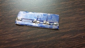
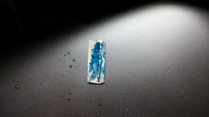
- Sharpie does not work as a solder mask, at least for reflow; flux readily dissolves the ink. Actually, the ink did seem fairly effective when I was applying the solder with the iron, but it started to lift with the paste, and once the flux was warm enough to flow the whole board was a tacky, blue mess. It naturally follows that the solder wicked all the way up the traces, as evident from the picture, but in this case that wasn’t a problem.
Once everything was relatively ready, I put the board in the pan[2] and turned it up to 375°F, which is reportedly slightly above the melting point for my solder. The board was placed off-center in the ring-shaped area directly over the heating element. The flux quickly turned liquid. After only a couple of minutes, the solder liquefied as well, and once it all seemed thoroughly reflowed, I turned off the heat, leaving the board in the pan as it cooled[3].
I brushed off the excess flux and scratched through the remaining film to the contact spots I made for power to the board. I connected up the gator clips and powered up. Nothing in either direction. Then I realized that I’d left the plane on the far side of the board untouched, causing the clips to be shorted. Whoops. Touching the clips to the points on the top side of the board allowed it to function properly.
It can be done!
Stuff I’ll keep in mind for next time:
- If more than a little solder ends up on a pad, it should probably be wicked off. A little is necessary; a lot can be problematic for placement.
- I’ve also read that, for small enough parts, unevenness between the pads can cause the component to stand on end instead of soldering properly, called “tombstoning”. Let’s try to avoid the parts that are especially prone (the hard-to-imagine-ly small 0402 and 0201 parts).
- Flux before placing. It may help keep the components in place.
- Experiment with mask materials before attempting to use one again.
Thanks to Club Cyberia for being a place other than my garage where I can make this stuff happen.
- [1]0.06 by 0.03 inches↩
- [2]To be perfectly honest, the board was in and out of the pan at least twice as I noticed things I’d forgotten to do, but was only allowed to fully heat when ready.↩
- [3]Cooling or quenching it suddenly is likely to damage the components or reduce the structural integrity of the connections.↩

