Nice coding. Has it got a name?
I have a self-clocking line/signaling code in mind. I don’t know what it’s called, and I’m having a rough time finding out.
The other night, I was trying to come up with a self-clocking signal that is simpler than Manchester codes to decode. What I came up with amounted to the above image. I felt like a genius. A signal that carries both clock and data, with all the clocks encoded in the rising edges and all the data a fixed time forward from the clocks. All one needs to re-separate them is a monostable (with a Schmitt trigger if the signal is dirty). No state information
Two seconds later, I thought, hmm, this is somehow too simple. Someone’s probably come up with it before. Oh, well. Since I’m a novice and came up with it independently, at least it must not be patentable…
Here’s a rundown of the encoding:
- Every bit is guaranteed to be made up of exactly two transitions; a rising edge and a falling edge.
- Each of these has “hold time” requirements depending on the hardware in use. The signal needs to be high for a minimum amount of time, tholdH, before switching to low for an edge to be detected, and vice versa, tholdL.
- The value of each bit is determined to be the value of the signal tread after the rising edge.
- Equivalently, the value of each bit is determined by the width of each pulse, with a narrow pulse (narrower than tread) indicating 0 and a wide pulse (wider than tread) indicating 1.
- Nominally, tread is the pulse width of a monostable triggered by the rising edge; actual implementation may vary.
- A 0 is read if the falling edge happens before tmin, generally as soon as possible after the rising edge (after first allowing tholdH).
- A 1 is read if the falling edge happens after tmax.
- Timing:
- The range tmin to tmax is defined by the transmitter as the range of valid values for tread at the receiver.
- tmin > tholdH + tholdL. A larger value allows the transmitter more time to encode a 0.
- tmax > tmin. A smaller value allows higher transfer speeds while a larger value allows higher tolerances on the receiver.
- If the last bit transmitted was 0, the rise for the next bit can start immediately since tholdL has already passed. The minimum duration is tmax.
- If the last bit transmitted was 1, the signal is driven low after tmax and held tholdL before starting the next bit. The minimum duration is tmax + tholdL.
- An arbitrarily long time is allowed between the end of one bit and the start of another as required by the application.
What I found out later is that a variation of this encoding is used in 1-Wire, a bus protocol for small, low-power devices. Unfortunately, as far as I can find, they don’t actually name this scheme. Argh!
If you know a name for this scheme, I’d love to hear an answer.
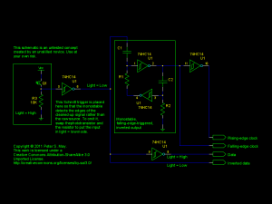
In the meantime, I’ve developed a couple of possibilities for a receiver, but haven’t tested any of them. I was thinking that this would be a fun protocol for devices that receive flashing messages from your computer monitor, much in the fashion of the Blinky POV but with only one sensor instead of two (since the clock and data lines are no longer separate). Through a bit of logic abuse, I’ve devised (but not tested) a decoder circuit that uses one 74HC14 and a few passives. I do truly wonder whether it would work…
Edit: A couple of notes (for myself) on the monostable in this circuit. It’s based on an older design that uses NAND gates from a CD4011 as its inverters. The notes for that version indicate that the output pulse width, in seconds, is 0.69(R1C1 + R2C2), or 2 × 0.69 × R1C1 if R1 = R2 and C1 = C2. I suspect that the coefficient (0.69 here) might be different with the newer part, but the rest is probably unchanged. (Experimentation is likely to follow.) Also, while there are easier monostables in the HC series (see 74HC221) as well as more well-known monostables in general (like the 555 monostable configuration), Schmitt inverters are (ab)used here because the application already needs one or two of them, leaving four or five left over without increasing the chip count. Plus, I already have a bunch of them and they can be had for as little as a quarter each, making this an interesting decoding option that doesn’t require a microcontroller.

