Archive

Concept

A simple one-directional level shifter is easy to build out of an NPN transistor and two resistors in the common-emitter topology, if the application doesn’t need to sink as well as it sources—that is, if a significant output impedance is acceptable when the output is high. If low impedance is needed for high output, an additional PNP transistor and two resistors[1] can be added, again in common-emitter topology, to re-invert the signal, but then the output low has the impedance instead.

To both source and sink with comparably low impedances, the obvious solution, if you’re properly equipped, is probably CMOS: Two complementary MOSFETs configured to pull the output either up or down, with similarly low impedance either way—or, more likely, a CMOS logic IC that does the same thing, but in a more compact fashion.

Still, there are some possible issues:

  • If you don’t keep a stock of (fairly well matched) N-channel and P-channel FETs around, you can’t really build a CMOS inverter out of them.
  • If all you have are 74HC-series ICs, the output voltage must be from 2V to 6V. If your output voltage is, say, 13V, this is a no-go.[2].
  • If the input high voltage is too much lower than the output voltage, a logic high may not register properly. A preliminary low-to-high shifter (such as the single-sided NPN thing from before, 3 parts) would be needed for each input.
  • If the input high voltage is too much higher than the output voltage, a logic high may do some damage to the IC. A preliminary high-to-low shifter (such as a resistive divider, 2 parts) would be needed for each input.

Incidentally, constructing a CMOS-like complementary output using discrete bipolar transistors is not advisable;  even short input transitions can cause high and low transistors to be on simultaneously for a non-trivial amount of time, a condition called shoot-through, which results in a massive current spike likely to damage both transistors and possibly other components. One way to avoid this condition is to add a resistance between the high and low sides, but then we’re back to the original problem. Shoot-through is evidently less of a concern with CMOS, partly because the FETs involved have better tuned and matched thresholds, and partly because a MOSFET is less subject to self-destruction via thermal runaway than a BJT.

Wanting to prototype something with an oddball push-pull 3.3V-to-13V switch led me to concoct an experiment using only stuff available at a reasonably well-stocked Radio Shack[3], with particular attention to ICs that provide push-pull outputs. So far I’ve tried configurations based on the original 555 timer[4] and the TL082 op amp.

My first experiments with the TL082 in Schmitt trigger configuration were not promising, but I’m suspicious something may have been connected wrong; the logic low never went below 1.15V, which happens to have been the reference voltage, half of 3.3V. Either way, the supply voltage had to read 17.3V for a high output of 13V.

In contrast, the 555-based Schmitt trigger appears to be a workable solution, as long as you can drive the chip 1.5V higher than the desired high output.
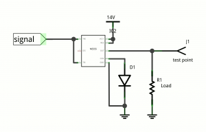
555 shifter

555 as a level shifter in just two parts (not including the load). Output is a roughly fixed amount below Vcc.

The output stage of the 555 is a push-pull output, but it is implemented with bipolar transistors in a traditional style, meaning both high and low sides are NPN transistors. This works, but at the cost of about 1.5V from Vcc. If you can pay that cost, it should work nicely.

In my experiments with the pictured circuit, using 1K for the load, the output was 12.5V for a 14.0V input. Similarly, it went up to 13.0V for 14.5V input, and 5.0V for 6.5V.

Apart from the 555, there is a diode to set the control voltage. The CV pin is essentially the top split of a 5K:5K:5K resistive divider from Vcc to ground. The splits of this divider set the high and low thresholds of the Schmitt trigger; they are CV (default 2Vcc/3) and CV/2, respectively. A silicon rectifier diode is added from the CV pin to ground, forming a crude shunt regulator with the internal resistors. This sets CV to about 0.6V and the low threshold to about 0.3V. This is suitable to make the input accept a clean signal directly from a 3.3V or 5V CMOS logic output. Adding a second diode in series with the first would double those levels, making input from a somewhat noisy source or from 5V TTL practical. CV could similarly be set using a Zener diode (in reverse) or by constructing a voltage buffer, but at that point you may just want to order a more suitable part.

So, there you have it—an imperfect but still practical low-impedance level shifter in just two parts.

  1. [1]or one resistor, with caveats I haven’t fully investigated
  2. [2]If you have the older CD4000-series ICs, however, up to about 18V is possible, as long as the inputs are brought within range.
  3. [3]For those of us who don’t have 24 hours to wait for progress.
  4. [4]Not the TLC555 they also carry, which may work better or worse.

While lying in bed last night, I was going over in my head everything I could recall having learned about getting a PCB[1] layout out of my computer and onto a piece of copper clad.

At this point in history I’ve managed to successfully iron a toner pattern onto a board only about three times, and each success came at the cost of around ten failures. The glossy photo paper is the only thing I’ve gotten to work; with magazine paper the image was too smudged to use, while with parchment paper hardly any of it stuck (though what did stick was high-fidelity). What has really been frustrating in this whole process is that there are too many variables and not enough correlation. I don’t know whether I haven’t been using enough pressure, waiting enough time, executing the correct motions, or using the right setting on the iron. For all I know, I could just have a crappy iron!

And everyone seems to have something different to try, with the most consistent results apparently from either (a) using a modified laminator for the toner transfer or (b) equipping for photoresist boards. Of the two, I would surely choose the photoresist, in part because it produces truly sharp results but mostly because the failure/success ratio seems to be lower. But both options involve buying new equipment (and in one case ruining it) with no guarantee of out-of-box success, and given the laser printer and copper-clads already in my possession, I’m already well in.

Anyway, I suddenly had an idea that, if it works, combines the even heat and pressure of a laminator with extremely low (new) equipment cost and increased controllability, the latter of which translates into more meaningful experiments and, when an experiment succeeds, more repeatable results.

What I decided was necessary is as simple as this:

  • The patterns are printed in reverse on the medium of choice—for me, it will be parchment paper since it already exists in my house.
  • The board is placed in alignment with the patterns on one or both sides.
  • The board and patterns are placed between two flat plates of rigid metal, such as steel.
  • The plates are bolted together and tightened at least to the point that nothing slides around.
    • Here, the sustained flatness of the plates is important so that the pressure remains fairly even across the entire pattern.
    • If you have any way to gauge it, take note of the tightness or pressure of the plates on the board. This is possibly one of the variables.
  • The oven is set to the target transfer temperature.
    • To be truly scientific about it, use an oven thermometer to ensure the knob is telling the truth.
    • The temperature is certainly one of the variables.
  • The oven is allowed to preheat until up to temperature.
    • My hypothesis is that a consistent result is probably easier to obtain from a preheated oven due to variances in rise time.
  • The plate apparatus is placed in the oven near the heat source.
    • If the apparatus can be hung sideways from the rack, do so allowing equal heat exposure to the two sides.
    • If the oven has a convection mode, it might be worth using.
  • A prescribed amount of time passes.
    • Another variable.
  • The apparatus is removed from the oven.
  • The apparatus is allowed (as by air) or forced (as by water) to cool to a safe temperature for handling.
    • Maybe another variable.
  • The apparatus is disassembled and the results are examined.
    • An effective transfer should stick well enough that it does not lift or flake when the medium is pulled away. Therefore, the medium can be pulled away without being exceedingly gentle.
    • If the result is unsatisfactory, a hypothesis is formed as to why that relates to one of the variables. The variable is adjusted and another attempt is made.

With this basic process in my head, I went to Chain Home Improvement Store to seek something I could use for the plates. What I found was square steel covers for electrical work boxes, in a flat variety with no punchouts. They already have holes for fasteners at two of the corners, and it was only $1 for the pair. I also got #10-24 stainless steel bolts and wingnuts which themselves totaled $4. This setup should adequately accommodate boards up to about 3 by 4 inches (for comparison, the standard Arduino footprint is 2.7 by 2.1 inches).

I now have all the equipment I think I’ll need to give this a shot, and that could happen as early as this weekend (and I’ll try to take photos). I really hope it works, not just because it would be convenient for me, but because it has the potential to lower the blood pressure of many other frustrated hobbyists.

  1. [1]printed circuit board
2-channel-power-Pch

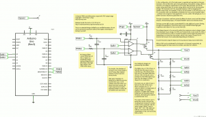
If it works as intended, this circuit should allow an Arduino to control 2 different output voltages via PWM.

(EDIT: The above is the second revision.[1] Note also that the above will not work as-is, except perhaps in the NPN or N-channel variants; it doesn’t account for the fact that the op amp outputs peak well below the voltage necessary to turn off a PNP or P-channel transistor.)

Out of nowhere I just happened to find an 18V wall wart in my junk box. The lack of such a thing makes it necessary for a PIC programmer to produce its 12-14V programming voltage some other way, such as with an adjustable regulator and a pair of 9V batteries or with a boost converter. Even so, a programmer for production-quality output must be able to adjust its own programming voltage as well as its own output supply voltage.

Read More

  1. [1]This version uses P-channel MOSFETs instead of PNP, and better explains the power requirements.
piculear Suite

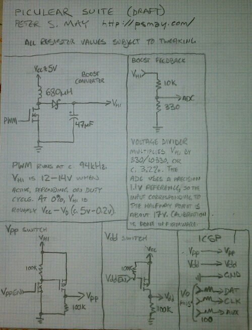
A suite of pieces that just might comprise a working PIC programmer when connected to an Arduino.

Years ago, while frustrated with my Microchip PICkit 2, which I only bought because of two failed attempts at building serial-port-based PIC programmer designs, I considered the possibility of a somewhat more open design that still had solid USB-based communications and the 5-to-13V boost converter, which was still kind of mysterious to me at the time.

Read More

I think statically typed programming languages are great. Why? Because in just about every dynamically typed language I’ve ever used in earnest—JavaScript, for example—at some point I’ve had to write a lot of code to verify that a value looks like a certain type (one often can’t get a full guarantee) in order to make assertions about the theoretical correctness and consistency of a program. Is that a string? An array? A number? I can’t tell you until I’ve looked. For better or worse, JavaScript will allow absolutely anything (or nothing at all!) as a parameter. Sure, it’s a simple way to implement polymorphic functions without a whole lot of fuss…at first. But most functions I write are intended to work on a set of values that is much, much smaller than the set of values it is not designed to work on.

At a medium-to-high level, this is a non-issue with static typing. I specify a function to operate on values of specific types, and the program won’t even compile if someone tries to pass something different.

Apologists for dynamic languages have pointed to the verbosity and inflexibility of having to specify the type of every single thing, but advances such as type inferencedetermining the type of something based on how it is usedand type-safe genericsfunctions and objects that can operate on arguments of arbitrary types if those types fit general criteriahave made it easier for programmers to convey all of the intended meaning without sacrificing too much flexibility or writing too many more words than necessary.

Another important point to consider is the failure mode of a program that isn’t written correctly. Inconsistencies in the use of values and types tends to be a compile-time error for static languages; they are caught before the program is even run. In a dynamic language like JavaScript, no static types are enforced per se, but using a value as if it is something it’s not can result in a run-time error in the best case[1] and instead often “succeeds”, producing unexpected results [2].

Of course, I don’t like the bits of the static languages that continue to allow type-unsafe behavior. In my opinion, the major violators are:

  • Static casts, such as Java/C# String s = (String)o for some Object o
  • Instance-of as a boolean operator (more of an accomplice than a criminal)
  • Inheritance-based polymorphism used in place of tagged unions
  • Null being an allowed (and often non-disallowable) value for any reference type

Starting with the last one: It really seems strange to me that we automatically allow null to be passed as an object, even if it is an artifact of C (a reference being implemented as a pointer, a null corresponds to a NULL pointer). I think it’s a more reasonable assumption that the object must be valid unless we say it’s optional.

What does this have to do with types? Null degrades the utility of a type if it can’t be disallowed by allowing a value outside the value space to be assigned to a variable of the type. When you pull a value back out, you may need to verify that it isn’t null before continuing. This sounds like that type identification routine I didn’t want to write in JavaScript!

Scala very nearly has it right, offering up the Option monad from the functional programming world, which more or less accepts either a value from an existing type or the solitary None value. However, Scala also still has null for Java compatibility. D’oh! C# does it exactly right, but only for value (“struct”) types, with a ? suffix on nullable types. Objects are still always nullable.

Some work has been done to paper over this in Java, including several disparate @NotNull/@NonNull/… annotations. The first problem is that these aren’t enforced by standard Java but only by third-party static analyzers (so I hear). The second is that they’re not the default, and they never will be without some massive shift in mindshare.

Static casts are another holdover from C. In C, they are how pointers change from one type to another. This is essential to much actual activity in C, in part because C lacks generics.

Take for example qsort(). This is a function that behaves very much generically: It takes a void pointer to an array of objects of a size provided as another argument, then uses a pointer to a function that compares two such objects, passed as void pointers themselves, to determine a sort order. There is no such thing as a “void” value; a void pointer could point to anything at all. You might pass an array of int, or perhaps an array of const char *. As long as the function you pass later is in agreement, the sort works equally well.

// Actual compare functions
int compare_ints(int a, int b) {
	return (a < b) ? -1 : (a > b) ? 1 : 0;
}
int compare_doubles(double a, double b) {
	return (a < b) ? -1 : (a > b) ? 1 : 0;
}

// What you pass to qsort()
// Note the explicit pointer casts
int compare_ints_vp(void * a, void * b) {
	return compare_ints( *((int*)a), *((int*)b) );
}
int compare_doubles_vp(void * a, void * b) {
	return compare_doubles( *((double*)a), *((double*)b) );
}

But who checks whether or not it does agree? The answer is nobody. You could accidentally pass a comparison for int with a compare function for double. The compiler will not catch it, because either function has the same signature, accepting two void *. By using an explicit cast, as the compare functions have to, you’re relieving the compiler of virtually all responsibility of checking that conversion.

And what’s the failure mode? An actual runtime error in the best of cases (probably a segfault), but often just reported success paired with some hard-to-track-down erratic behavior. Seeing a pattern?

Thankfully, the JRE (Java) and the CLR (.NET) do care about types. The result isn’t always pretty, but it’s far more deterministic: If an object is cast to something that it isn’t, an error (exception) is guaranteed. But in Java, it isn’t a checked exception, and C# doesn’t do checked exceptions, so if a cast fails in this way, you can catch it, but the compiler won’t make you. And, of course, it often defers what should be a static type error to run time.

Like with C, much of the use of explicit casts in Java is to simulate generics; type-erasing generics were added a couple of major versions ago, but code from before that era is still alive and kicking. For example, before Java 1.5, java.util.List<T> was available only as java.util.List, which essentially always behaved as java.util.List<java.lang.Object> does now. If you had a List containing nothing but String objects, you couldn’t express it, so instead of someList.get(n), you’d do (String)someList.get(n), counting on convention and luck for any type safety.[3] The addition of generics dealt with the worst of this usage.

Java and similar languages eschewed the C union, citing that its legitimate usages[4] had been supplanted by inheritance-based polymorphism.

For example, say you have a heterogeneous List, in which each element is a String, a Number, or a Date. The types and orders are not known at compile time, but it is known that any of these three types can be elements without a problem. There is no direct expression for this in Java. The polymorphic approach would be to use a List with an element type of the nearest common ancestor, which is Object. This will work, but the code will need to incorporate explicit logic to determine that each member is allowed, because the compiler now allows any Object, not just the ones we want. D’oh again.

In the process of doing this checking, there’s something else that feels a little loose. In essence, there is a sequence that should always result in sane cast usage. First[5], you check the type membership—if it is this type, jump to the second step; otherwise, skip the rest[6]. Second, you cast the reference. Third, you execute code that uses the reference.

The most important part is that if the first step is a negative, you never try to cast the reference and you never attempt to use the cast reference.

Here’s what a bunch of these look like chained together, along with a null check:

void doSomethingWith(Object o) {
	// ... code that doesn't care about the object type ...
	if(o == null) {
		// Run-time check :-(
		throw new NullPointerException();
	}
	else if(o instanceof String) {
		String s = (String)o;
		// ... handle the string ...
	}
	else if(o instanceof Number) {
		Number n = (Number)o;
		// ... handle the number ...
	}
	else if(o instanceof Date) {
		Date d = (Date)d;
		// ... handle the date ...
	}
	else {
		// Run-time check :-(
		throw new IllegalArgumentException();
	}
	// ... code that doesn't care about the object type ...
}

It shouldn’t be this painful to write sound code. In this matter, Scala is the only one that does it right. The important thing to note is that Scala’s pattern matching combines all three of the steps into one; the same syntax that checks the type also casts it for you and runs contingent code.

def doSomethingWith(o: Any) {
	o match {
		case s : String => ... // handle the string
		case n : Number => ... // handle the number
		case d : Date => ... // handle the date
		case _ => throw new IllegalArgumentException()
	}
}

The only thing I think could be better about the above code would be the ability the omit the default case. (You can, but the failed match is a run-time exception.) Alas; Scala doesn’t do union types[7] and it still allows null.

I’ve drafted multiple language specs to help heal these wounds while remaining essentially C-esque or Scala-esque in syntax[8]. Hopefully I’ll succeed in implementing one of them at some point…

  1. [1]like trying to call a method on an object or non-object that doesn’t implement it
  2. [2]function f(x){return 100+x} results in either 123 or “10023” for f(23) and f(“23”); generally only one of these is the expected behavior
  3. [3]The Java compilers that support generics literally just do this for you, for the sake of backward compatibility. It’s kooky, but I’m fine with it as long as it’s the compiler’s job.
  4. [4]It was popular to use unions to destructure a value’s in-memory representation, for example, a union of a uint32_t superposed on an array of four bytes, but this usage is non-portable and generally contraindicated.
  5. [5]If the reference happens to be declared volatile, copy to a nonvolatile variable before proceeding.
  6. [6]and, optionally, run code that only happens if the type check fails
  7. [7]A similar effect can be had from case classes, but it involves surrogate objects.
  8. [8]Lisp is a nice idea, I think, but the syntax is a little abhorrent to non-theoreticians.

This circuit provides a pulse-sequencing capability using the control voltage inputs of the 555.

The circuit described here triggers three (or an arbitrary number) monostables with differing but related widths. What’s different about this one than others I’ve seen is that this circuit has only one timing signal; in particular, there is only one RC network among all, which could potentially reduce the parts count and, more importantly, increase consistency among the timers.

The timing network is actually sort of a modified RC using a transistor and a voltage reference to charge the capacitor with a constant current. The timing is determined by the base voltage of the PNP transistor, the resistance at the emitter resistance, and the capacitance at the collector. The voltage drop across the resistor is the Vcc – Vb + Veb[1]. As long as none of these three values vary significantly in the application, the resistor’s voltage drop can be considered constant. If the resistor is, as expected, also constant, then the current through it is constant as well: I = V/R. The transistor will adjust as necessary, if possible, to maintain that current through the transistor[2]. If the supply voltage is well regulated, the base voltage can be set with a voltage divider.

The output of this constant current timing network, in contrast to the tricky curve of a regular RC network, is a linear ramp. This makes it easier to calculate the desired control voltage for each monostable. In the example above, the control voltages are 1V, 2V, and 3V, where the 1V and 2V timers produce a pulse exactly 1/3 and 2/3, respectively, the width of the 3V timer pulse. The values need not be this regular. A normal RC network could be substituted if you’re willing to do the math.

The monostable with the longest delay should have its discharge pin connected with its threshold pin in order to discharge the capacitor.

This approach gets a little unfortunate where setting the control voltages comes in. The CV is preset internally with a three-step resistor divider network. The CV itself is roughly 5k from Vcc and roughly 10k from ground. If I’ve done the math correctly, this is equivalent to a 2Vcc/3 supply through a 3.3k resistance. This means that you can’t trivially set the control voltage with a divider—something with a low (ideally zero) output resistance is necessary. Here are some things that might be worth trying:

  • Resistor divider with proper buffer (2 resistors, 1/4 to 1 op amp IC). If you’re not willing to complicate the calculations, an op amp can output the same voltage as the input, with no base-emitter drop. As a bonus, it’s an op amp, which is capable of a whole lot more. If restricted to Radio Shack, I’d pick up two TL082 JFET dual amps (or an LM324 quad if they’re out), then use three of the amps with a resistor ladder to set CVs and the one left over to upgrade the current source. I’d guess this is the option that would involve the least hair-pulling. (Edit: An example of a buffered resistor divider, complete with redone current source, in terms of a 7805 voltage regulator. Would require a supply voltage above 7 volts or so, but it’s an easy out in 2-3 ICs and about 10 resistors, plus the transistor and RC already in the circuit.)
  • Resistor divider with unity gain transistor (2 resistors, 1 NPN transistor). Similarly to the current source, the emitter voltage is a nearly fixed drop below the base voltage.
  • Trimmer (1 potentiometer, potentially up to 2 biasing resistors) if you’re okay with a bit of tuning.
  • Linear voltage regulators/references. Would probably work really well, but might be expensive depending on where you buy[3] and in this case requires a fairly small one (probably around 1V). The LM317 can be treated as a precision 1.25V drop, as long as the minimum load requirement is met.
  • Diode drops (1 diode). In the simulator, I was able to get the circuit to work with a ladder of diode drops for the control voltages (i.e., around 0.7, 1.4, and 2.1V). I’ve read that in practice this doesn’t work nearly as well.

By the way, the intended purpose is to trigger some D flip-flops to read serial data in an experimental line encoding I’ve conceived. It’s a variation of one I discussed way back, but the initial rising edge is followed by three bits of data before the mandatory fall. If it works, it could mean a simple output interface for PCs (e.g. via monitor or sound card) to devices that only understand data in terms of data, clock, and latch. What does this mean? You guessed it—semi-headless 74HC595 displays. (Okay, maybe not so much, but that’d at least be a good way to test it.)

This circuit is available on the Falstad simulator.

  1. [1]Veb may vary slightly depending on current, but is roughly 0.7V under normal circumstances.
  2. [2]Up to near the max collector voltage, in this case slightly lower than the emitter voltage.
  3. [3]LM317 is $3 at Radio Shack, but way cheaper online, especially in a TO-92 package.

No guarantees, but it worked in the simulator.

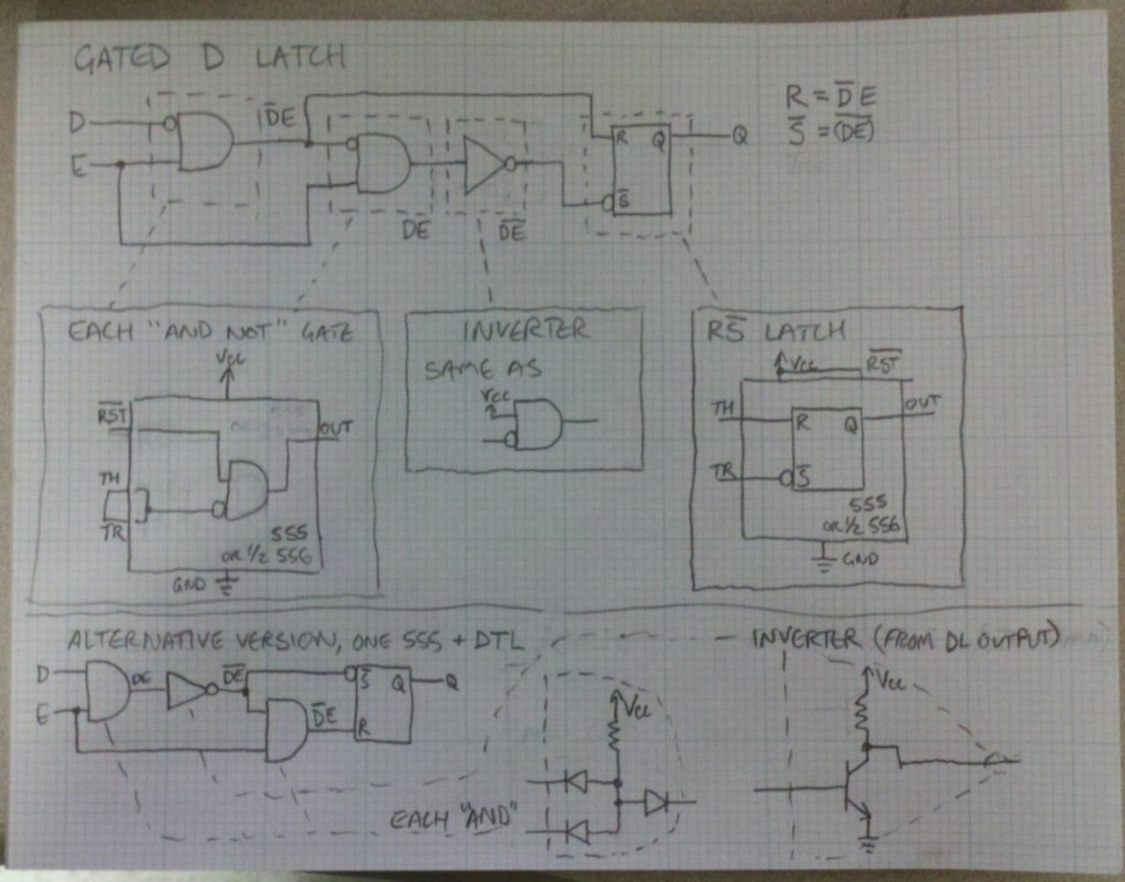
Today, figured out how to make a (possibly low-speed) transparent D latch out of an R-/S latch, plus a couple of logic gates, and an inverter. Each of these four things can be constructed from a 555 timer (or half of a 556). Alternatively, each of the gates can be replaced by three diodes[1] and a resistor, and the inverter by an NPN transistor and a resistor. Not pictured is the AC coupling[2] on the E input that would make this an edge-triggered flip-flop instead of a latch.

The significance of this is that a D flip-flop, a 1-bit static RAM and an important element of sequential logic, can be constructed very easily with stuff readily available from Radio Shack, which doesn’t stock logic ICs anymore but does carry 555s and 556s (as well as diodes, resistors, and transistors). Naturally, I have the best interests of the impatient experimenter in mind. :-)

  1. [1]With Schottky diodes you could probably get away with omitting the output diode.
  2. [2]In this case, an RC highpass is used, an inline capacitor of about 0.1µF followed by a 10kΩ pull-down resistor.

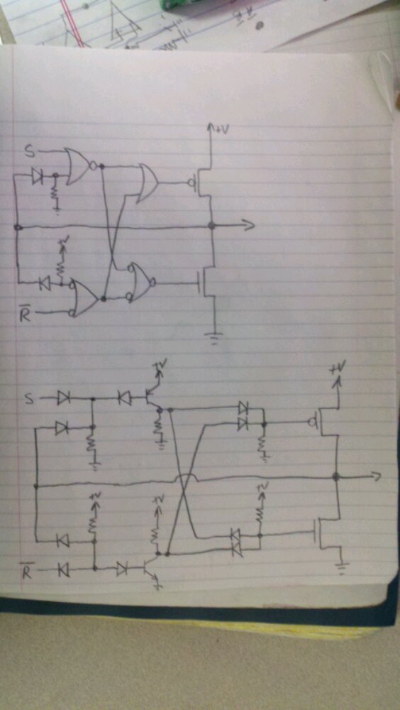
This circuit has not been tested. It might work. It might not. Who knows? All diodes should probably be Schottky.

I contrived a diode-transistor logic (DTL) circuit for a SR latch[1] with a CMOS push-pull output and a break-before-make mechanism to prevent simultaneous push and pull (shoot-through). I have no idea whether it actually works and there are probably easier ways to do it, but it was kinda fun.

The upper schematic lays out the concept in terms of OR gates with different inversions (clockwise from upper left: NOR, OR, AND, NAND). The output is fed back into the inputs through diode-resistor level shifts so that the one being fed into the high side is high when the output is high but low if the output is either low or off (high-impedance), and the one into the low side is low when the output is low, but high if the output is high or off. This feedback should prevent either output FET from turning on until the complement is turned off (or close to off).

The lower schematic is the upper schematic rendered in diode-transistor logic. The lower-left gate, a NAND, is implemented using the textbook DTL NAND with an NPN transistor. The NOR in the upper left is actually the same as the NAND, but with the diodes reversed and a PNP on the output. Note that in both cases the feedback diode-resistor shift is now part of the gate itself. The other two gates are just diode logic since OR (upper right) and AND (lower right) can be implemented without a transistor on the output.

This contrivance is for a power logic buffer; the intended supply voltage would be somewhere from 12 to 48 volts and the current capacity on the output MOSFETs would be at least a couple of amps. I haven’t tested the thing. Please don’t use it, except in test circumstances, unless you know what you’re doing.

  1. [1]Technically, an S AND NOT R latch.

The following draft description runs down the basics for a single port that allows the direct connection of Sega Genesis controllers and connection via a mostly passive adapter for several other systems’ controllers, including NES, SNES, PlayStation and PS2, Nintendo 64, and GameCube. Additional styles could be added later, and a structure is made available for controllers custom-built to this spec. Read More