It’ll put a tone in your head
The motion sensor circuit I previously contrived works, but there’s a problem: The buzzer is really quite loud—loud enough to potentially cause trouble in the middle of the night. I’ll need to make a quieter one.
Fortunately, it’s none too difficult to make a device that produces a tone. All one needs to do is make an oscillator, a circuit that produces some kind of output wave, that oscillates at a frequency within the range of human hearing (per Wikipedia, roughly 20Hz to 20kHz), and then route its output to a speaker or piezo element.
Precision is not of the essence in this application; 500Hz and 5000Hz would probably be equally adequate for the job. This looks like a job for an astable multivibrator, which is a circuit that produces a cyclic square wave, with an RC network, which is a circuit that uses the rise or fall of charge in a capacitor via a resistor as the basis of timing.
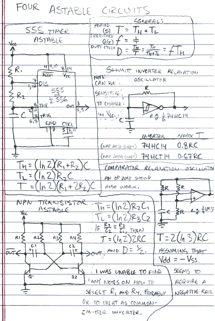
The above note summarizes four methods I was able to locate easily for building astables out of different components. Each of the four uses an RC network (or two) as its timing element. Some additional notes:
| Circuit | Timing components | Other components | High time factor | Low time factor | Period factor | Other notes | Parts count |
|---|---|---|---|---|---|---|---|
| 555/556 astable | R1, R2, C1 | 555 or 1/2 556 IC, capacitor for control pin (10nF nom.) | (R1 + R2)C | R2C | (R1 + 2R2)C |
|
|
| Two-NPN astable | R2, C1, R3, C2 | 2 NPN transistors, 2 collector resistors | R2C1 | R3C2 | R2C1 + R3C2 |
|
|
| Schmitt inverter relaxation oscillator | R, C | Schmitt-triggered inverter (e.g. 1/6 74xx14) | Not adjustable | Not adjustable | RC |
|
|
| Comparator relaxation oscillator | R, C | Voltage comparator or op amp (e.g. 1/4 LM339), 2 equal resistors for reference voltage division | Not adjustable | Not adjustable | RC |
|
|
Since the current application doesn’t have a negative supply, the comparator astable is out. Since it operates on 9V, the Schmitt inverter won’t be the best choice, either. That leaves the 555 and NPN astables. I’m fully equipped to use either one. Which I choose is likely to depend on how many 555s I have on hand and how many I’m willing to part with (I need to make two of the motion sensors); I have a pretty solid supply of discrete transistors but probably fewer than ten 555s at the moment.
Anyway, it’s good to know there are options!
